Chopper-stabilized operational amplifier and method

a technology of operational amplifier and stabilizer, which is applied in the direction of differential amplifier, amplifier with semiconductor device/discharge tube, amplifier details, etc., can solve the problems of large power consumption, unchopping, and output signals of core amplifiers, and achieve low noise 1/f and low offset drift

Active Publication Date: 2007-12-18
TEXAS INSTR INC
View PDF5 Cites 13 Cited by
  • Summary
  • Abstract
  • Description
  • Claims
  • Application Information

AI Technical Summary

Benefits of technology

[0014]It is an object of the invention to provide an improved operational amplifier design which avoids the need to provide a very narrow range of bias voltages in a folded cascode circuit in order to provide both low 1 / f noise and low offset drift.
[0015]It is another object of the invention to provide an improved chopper-stabilized operational amplifier having both low 1 / f noise and low offset drift.
[0016]It is another object of the invention to provide an improved chopper-stabilized operational amplifier having both low 1 / f noise and low offset drift, and also having relatively low power consumption.
[0017]It is another object of the invention to provide an improved chopper-stabilized operational amplifier having both low 1 / f noise and low offset drift which requires only two main amplifier stages to achieve acceptably high open loop gain.
[0018]Briefly described, and in accordance with one embodiment, the present invention provides an amplifier circuit including an input chopping circuit (26) for chopping first (7) and second (8) input signals, a transconductance stage (27) for amplifying an output of the chopping circuit (26) and applying it to the input of a folded cascode stage (28) and to the input of an un-chopping circuit (33) and also to the input of a chopper-stabilized gain boost amplifier (32) in the folded cascode stage (28). The output of the un-chopping circuit drives sources of cascode transistors (49A,50A) of the folded cascode stage. The gain boost amplifier includes another transconductance stage (71A,B) having another un-chopping circuit (88) coupled to the gate of one of the cascode in transistors (50A) of the folded cascode stage (27). The drains of the cascode transistors of the folded cascode stage drive a class AB output stage. The amplifier provides both highly linear operation and low 1 / f noise.

Problems solved by technology

The above-mentioned ordinary chopper-stabilized operational amplifiers provide low 1 / f noise and low offset drift, but have the disadvantage that the output signals of the core amplifier, which may undergo large magnitude voltage swings (depending on the loop gain), must be un-chopped, i.e. “un-swapped”, at the chopping frequency.
Therefore, the prior chopper-stabilized operational amplifiers have slow signal settling, and a large amount of power consumption is required to keep them operating properly at the chopping frequency.
This results in complex circuitry and high power consumption.

Method used


Image

  • Chopper-stabilized operational amplifier and method
  • Chopper-stabilized operational amplifier and method
  • Chopper-stabilized operational amplifier and method

Examples


Embodiment Construction

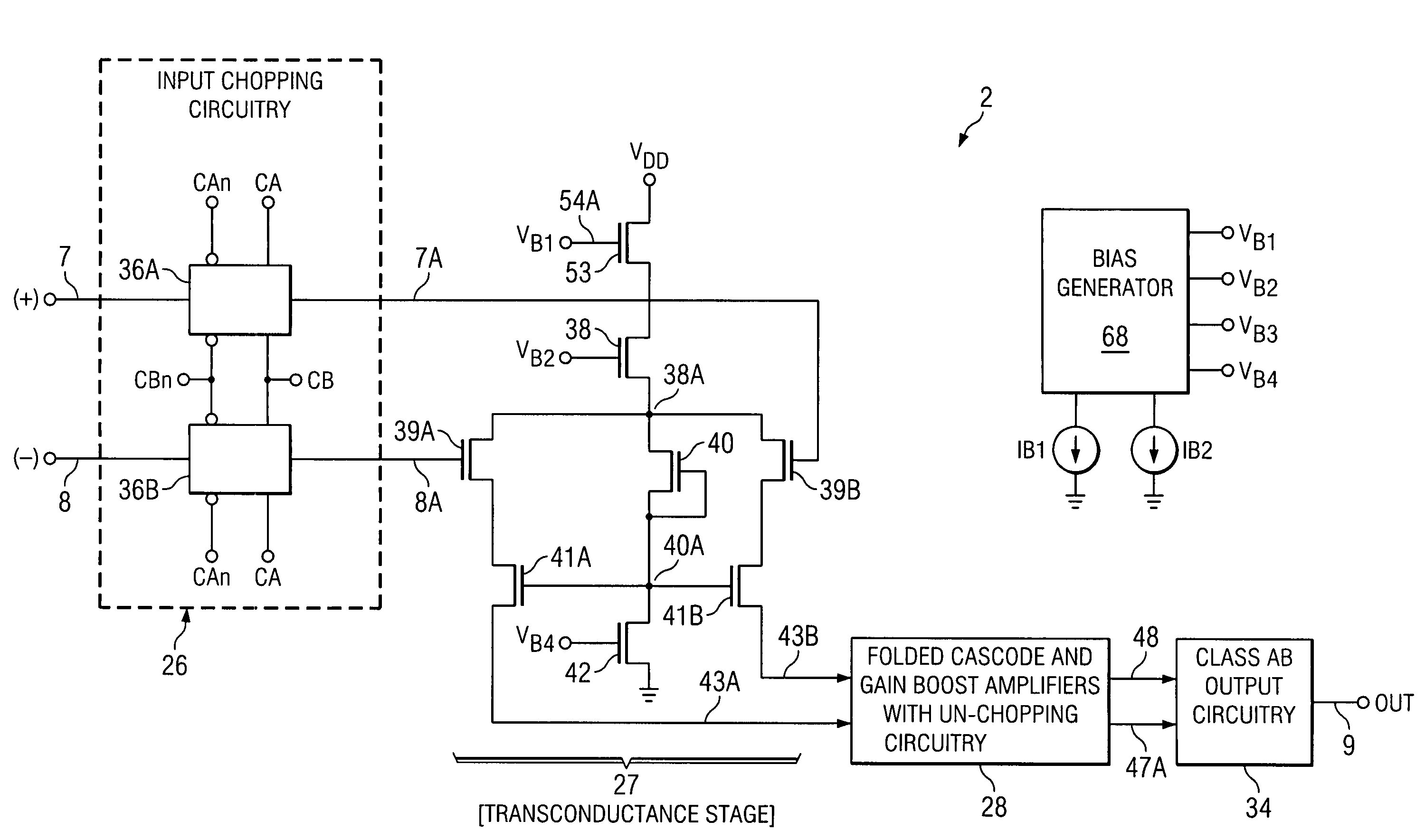
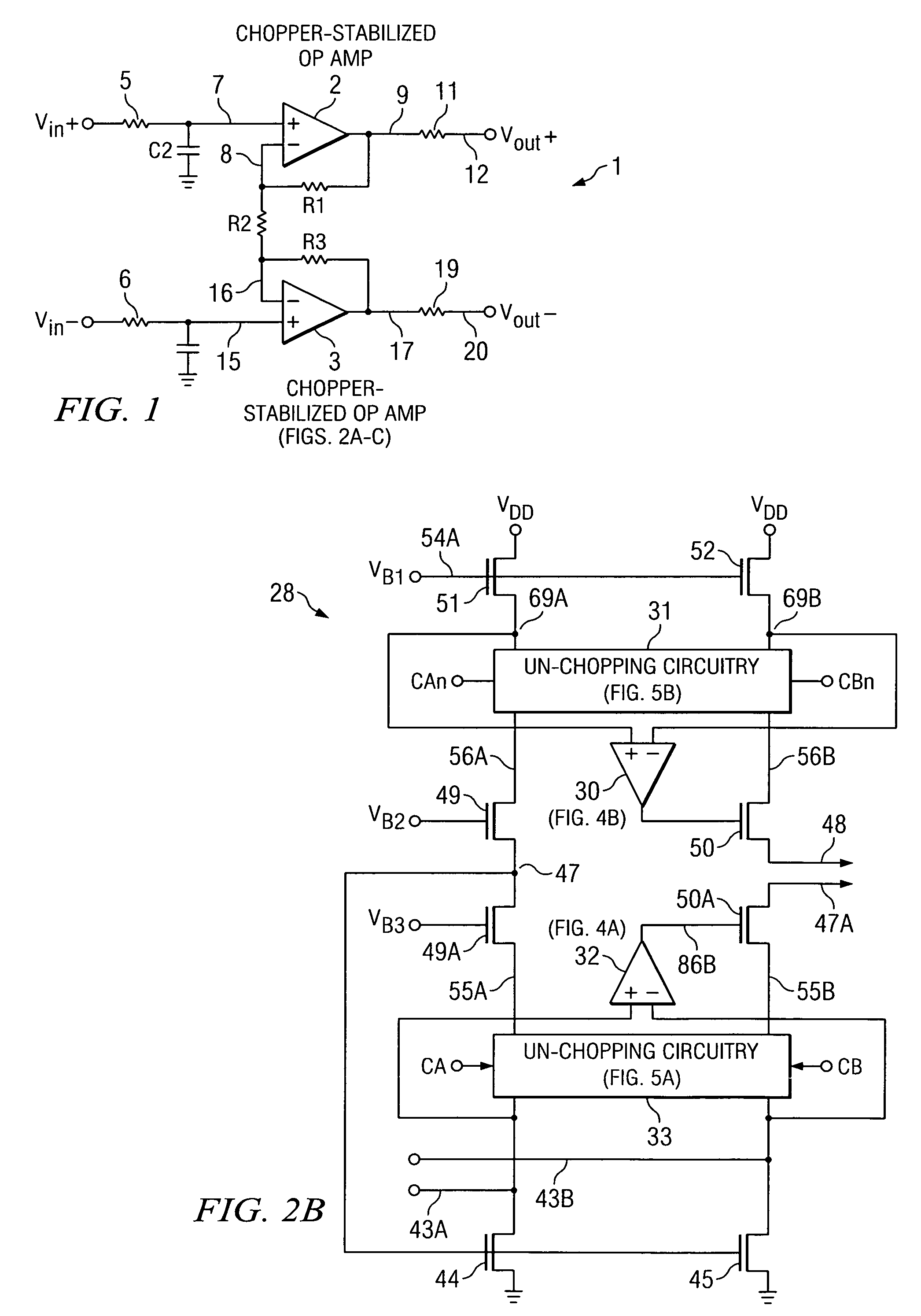
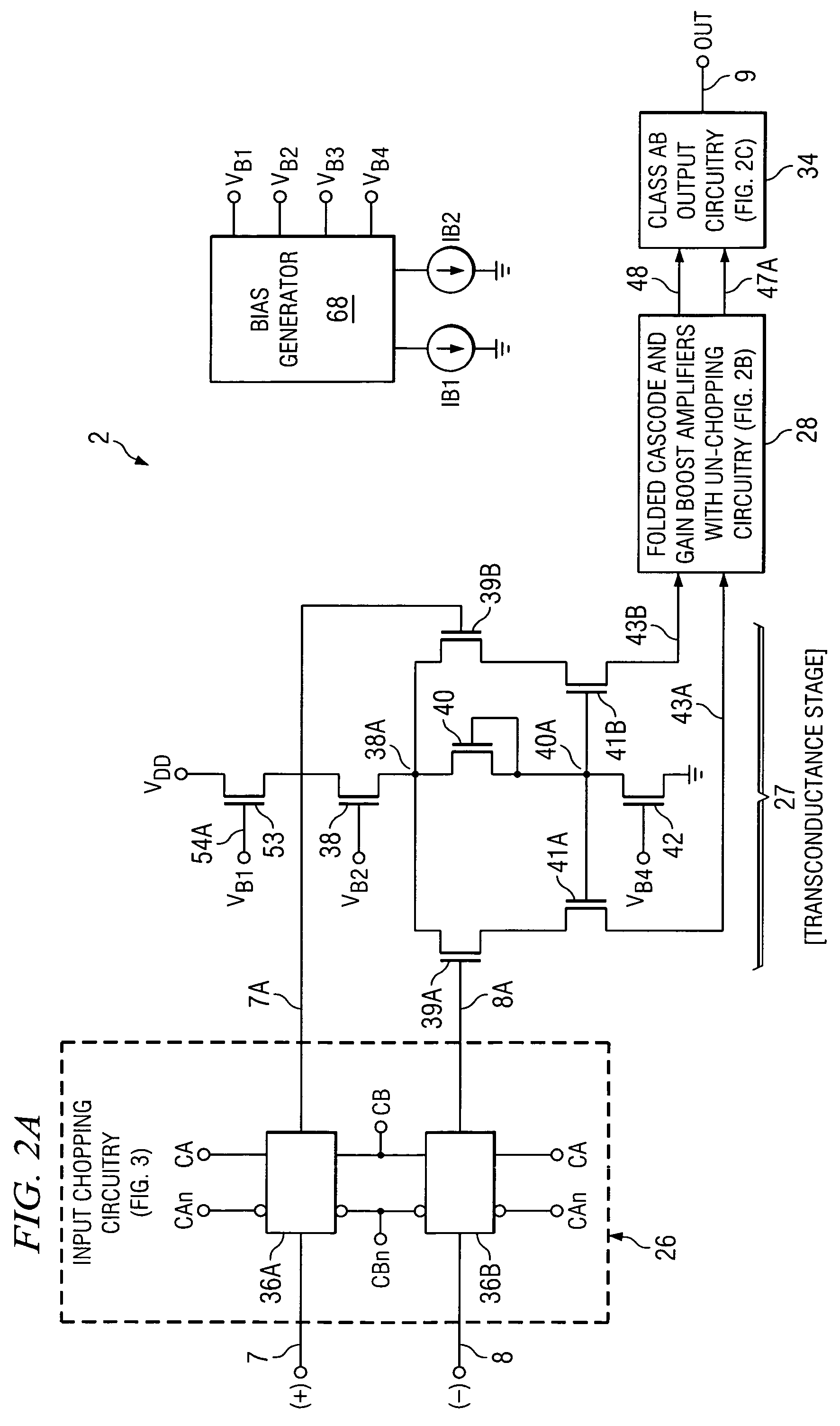
[0035]Referring to FIG. 1, an instrumentation amplifier 1 includes an input terminal receiving an input signal Vin+ and coupled by a resistor 5 and conductor 7 to the (+) input of a chopper-stabilized operational amplifier 2. Another input terminal receiving an input signal Vin− is coupled by a resistor 6 and conductor 15 to the (+) input of another chopper-stabilized operational amplifier 3. An implementation of chopper-stabilized operational amplifier 2 is shown in FIG. 2. Chopper-stabilized operational amplifiers 2 and 3 are the same. The (−) input of chopper-stabilized operational amplifier 2 is connected by conductor 8 to one terminal of each of resistors R1 and R2. The other terminal of resistor R1 is connected by conductor 9 to the output of operational amplifier 2 and to one terminal of a resistor 11, the other terminal of which is connected to conductor 12 on which in output signal Vout+ is produced. Similarly, the (−) input of operational amplifier 3 is connected by conduc...


PUM


Abstract

An amplifier circuit includes an input chopping circuit for chopping first and second input signals, a transconductance stage for amplifying an output of the chopping circuit and applying it to the input of a folded cascode stage, to the input of an un-chopping circuit, and to the input of a chopper-stabilized gain boost amplifier. The output of the un-chopping circuit drives sources of cascode transistors of the folded cascode stage. The gain boost amplifier includes another transconductance stage having another un-chopping circuit coupled to the gate of one of the cascode transistors of the folded cascode stage. The drains of cascode transistors of the folded cascode stage drive a class AB output stage. The amplifier provides both highly linear operation and low 1 / f noise.

Description

CROSS REFERENCE TO RELATED APPLICATION[0001]This application claims the benefit of prior filed now abandoned U.S. provisional application Ser. No. 60 / 698,754 filed Jul. 13, 2005 entitled “Chopper-stabilized OPAMP” by Shang-Yuan Chuang.BACKGROUND OF THE INVENTION[0002]The present invention relates generally to chopper-stabilized amplifiers, and more particularly to a way of providing lower-cost operational amplifiers having both low 1 / f noise and low drift.[0003]In conventional chopper-stabilized operational amplifiers, the externally applied differential input signal is “chopped” so as to reverse its polarity in response to each pulse of the chopping signal before being applied to the input stage of the “core” amplifying circuitry. This causes a corresponding reversal of the polarity of the differential output signal produced by the amplifying circuitry. If the externally applied differential input signal is zero but the input transistors of the input stage are slightly mismatched s...

Claims


Application Information

Patent Timeline
Patent Type & Authority Patents(United States)
IPC IPC(8): H03F1/02
CPCH03F3/45968H03F3/45
Inventor CHUANG, SHANG-YUAN
Owner TEXAS INSTR INC
Why Eureka
Try Eureka