
Retractable column and method of forming

a column and retractable technology, applied in the field of support columns, can solve the problems of poor interconnection of tower sections, poor connection of tower sides, and structure formation methods that were used in this apparatus and method, and achieve the effects of improving the load bearing capacity, and reducing the risk of falling

Inactive Publication Date: 2007-12-25
TOWER SOLUTIONS
View PDF33 Cites 16 Cited by
  • Summary
  • Abstract
  • Description
  • Claims
  • Application Information

AI Technical Summary

Benefits of technology

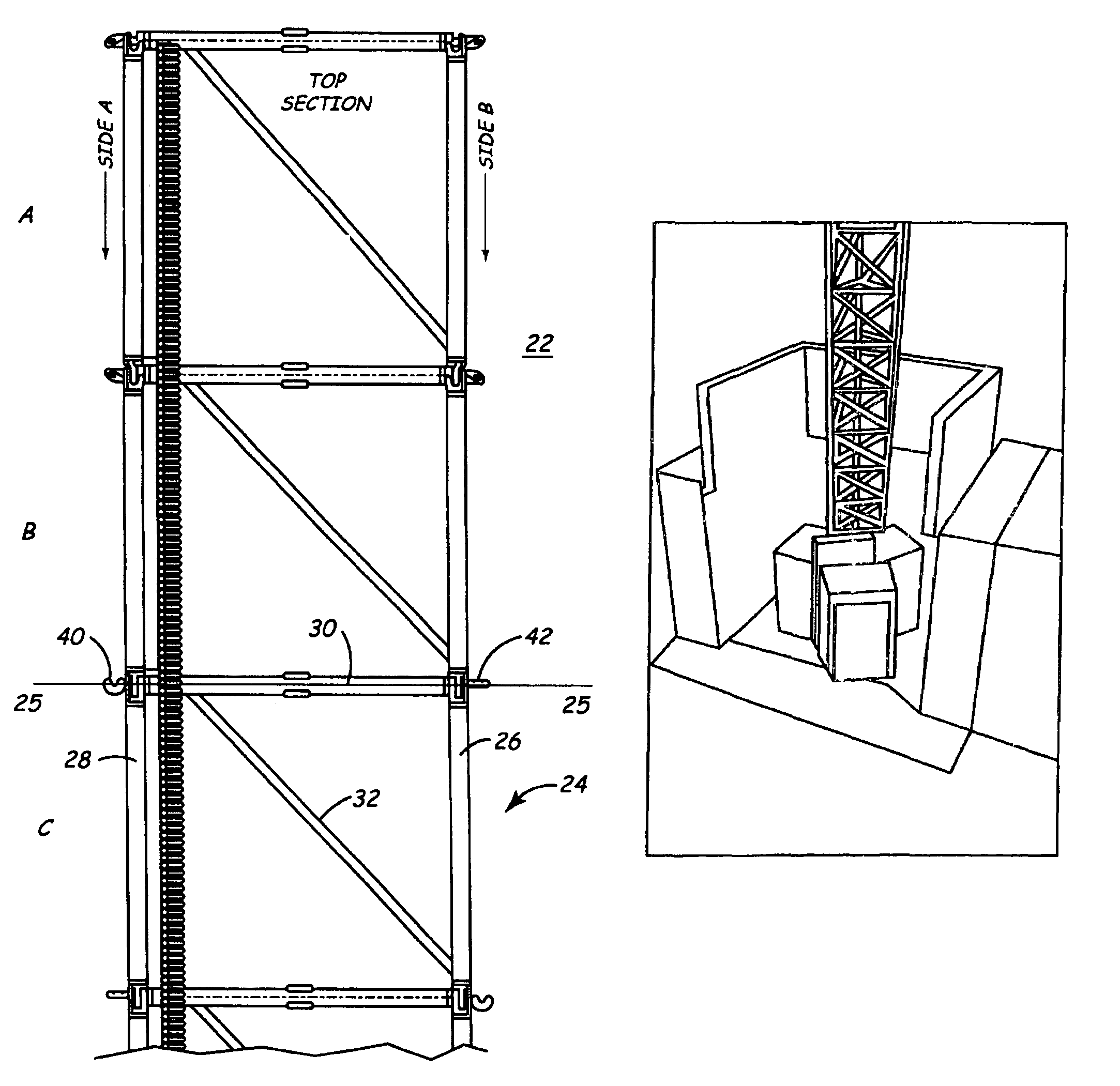
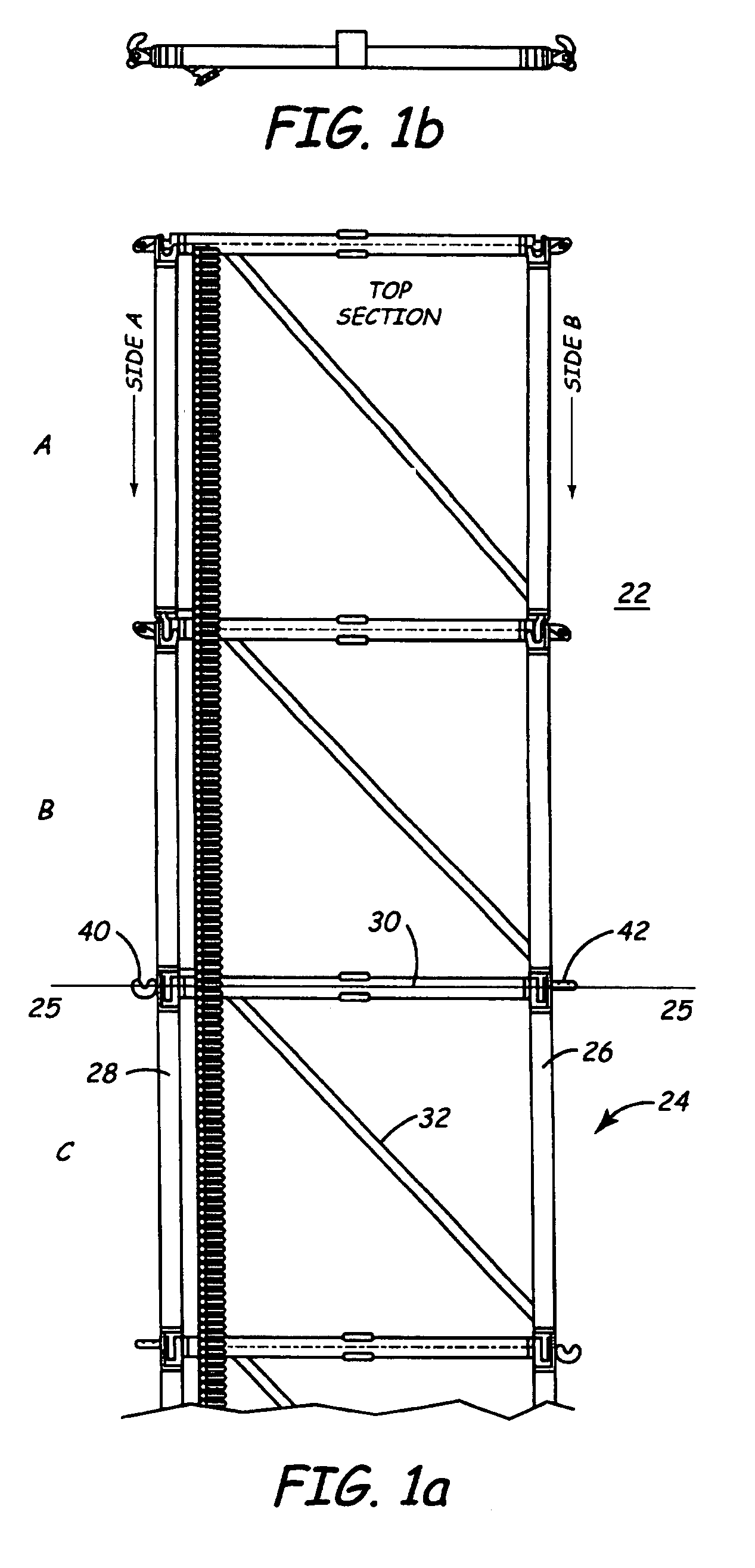
[0007]The present invention is an improved retractable tower which fills a variety of useful functions known in the art and which meets the needs in the art by providing greater stability and resistance to sheer caused by wind, ice, snow, and other adverse weather conditions, which provides a sturdier structure and which increases the load bearing capacity. The present embodiment accomplishes these needs by incorporating a number of new features, among others, an improved chain connection member, an improved guide system, an improved support and connection system, and an improved take up mechanism. These systems function individually and in combination to form a more secure locking engagement with the adjacent section chains, and to form a more structurally sound and stable tower.

Problems solved by technology

The structures that were formed using this apparatus and method, however, were subject to poor interconnection of the tower sections.
The poor connection of the sides of the tower was caused in part by poor alignment of the section chains, and through the hooks, as the sides were raised.
Poor alignment of the adjacent sections resulted in a poorly constructed tower; when a large amount of stress was placed on the poorly aligned tower, it sometimes resulted in the sheering of the pins holding the tower.
The sheering of the pins resulted in a low structural integrity for the tower.
These problems increased the difficulty in using towers systems of this type and also increased safety concerns and dangers.

Method used


Image

  • Retractable column and method of forming
  • Retractable column and method of forming
  • Retractable column and method of forming

Examples


Embodiment Construction

[0048]Additional features of the apparatus of the present invention will become more fully apparent and understood with reference to the above-referenced drawings, this description, and the appended claims, including the described embodiments of the extendable support column, and the description of erecting the device.

[0049]The accompanying Figures and descriptive material depict and describe embodiments of the present invention, including features and components thereof. With regard to fastening, mounting, attaching or connecting the components of the present invention to form the device or apparatus as a whole, unless specifically described otherwise, the invention may incorporate or use conventional fasteners such as screws, nut and bolt connectors, etc. Unless specifically otherwise disclosed or taught, materials for making components of the present invention are selected from appropriate materials such as metal, metallic alloys, fibers, fabrics, plastics and the like, natural o...


PUM


Abstract

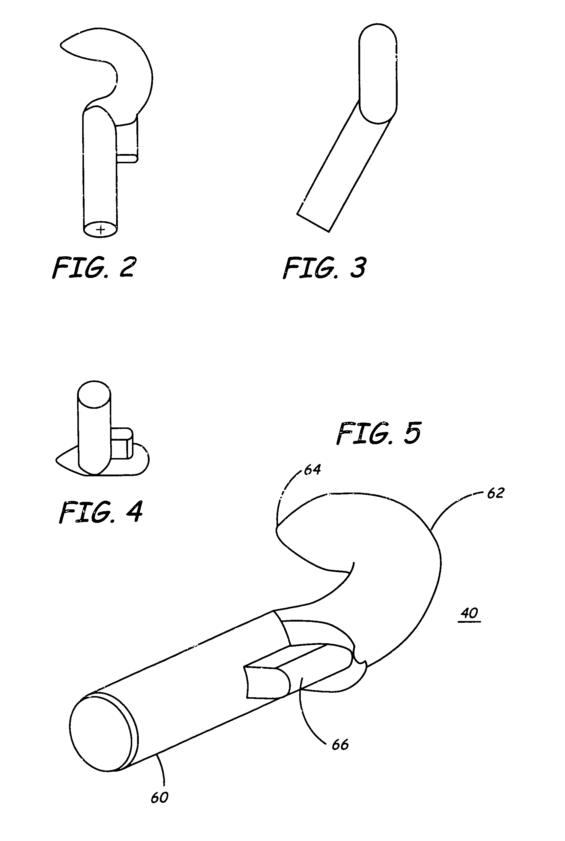
The present invention is an improved apparatus and method for forming a retractable tower or column. The present invention includes pointed hooks wherein the hooks are attached to each section of a section chain, one in a horizontal direction and one in an off-set manner. The section chains are placed on a take up mechanism in an operable position and then raised utilizing a motor. As the section chains are raised, they are guided by a guide tower, rollers, shims, and gear racks into a position whereby hooks from adjacent sections of the section chains form coupled engagements. The coupled engagement of the hooks of the sections of each adjacent section chains thereby form the column.

Description

[0001]This application claims the benefit of Provisional Application Serial No. 60 / 234,624, filed Sep. 22, 2000.FIELD OF THE INVENTION[0002]This invention relates generally to support columns, and more specifically, to an improved retractable support column for use in supporting overhead structures that can be extended from a portable or fixed in place platform.BACKGROUND[0003]Link structures that can be linked together to form a rigid structure are well known in the art. Structures of this kind may be used to form a platform to elevate a person or equipment, to form a bridge to permit a user to pass over an obstacle, or to form a dock. Additionally, such structures have been used in space applications to extend a flexible sheet of material or to form a tower as a structure in space. See U.S. Pat. Nos. 2,661,082, 3,397,546, 4,024,595, 4,089,147, and 4,237,662.[0004]Retractable towers of this kind may be further utilized as a portable telecommunications tower, wherein various sights ...

Claims


Application Information

Patent Timeline
Patent Type & Authority Patents(United States)
IPC IPC(8): B66C23/32B66C23/30E04H12/34B66F3/06E04G1/22E04G11/48E04H12/18F16S3/04
CPCB66F3/06E04G1/22E04H12/345E04H12/185E04H12/00E04G11/48E04H12/18E04H12/34E04H12/344
Inventor OLSEN, STEVEN A.
Owner TOWER SOLUTIONS
Learn More