

Pressure-pulse therapy apparatus
a technology of pressure pulse and apparatus, applied in the field of apparatus for pressure pulse therapy, can solve the problem of loss of pressure pulse energy
- Summary
- Abstract
- Description
- Claims
- Application Information
AI Technical Summary
Benefits of technology
Problems solved by technology
Method used
Image

Examples
second embodiment
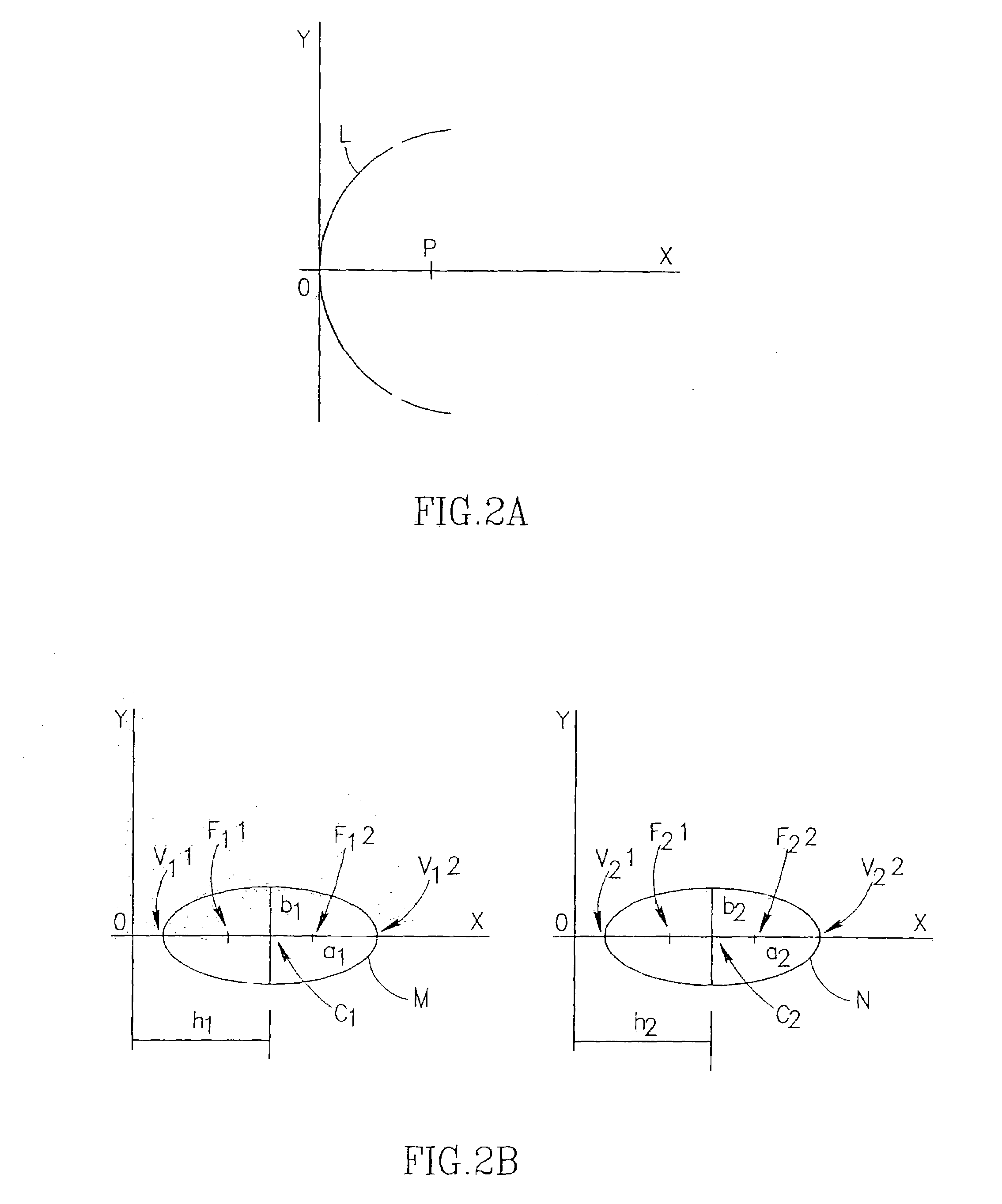
[0190]Reference is now made to FIG. 5, which schematically illustrates pressure-pulse therapy apparatus 100, in accordance with the present invention. Pressure-pulse therapy apparatus 100 includes a generally, but not exactly, parabolic center section 114, having a focal zone P′, generally around point P. Focal zone P′ can be determined as follows: a collimated propagation impinging on generally parabolic center section 114 will be directed as focal zone P′, thus defining focal zone P′. Preferably, focal zone P′ is within the reflector's dome.
[0191]Preferably, pressure-pulse therapy apparatus 100 further includes a generally, but not exactly, ellipsoid ring section 116, having a proximal focal zone F1′, which generally coincides with P′, and a distal focal zone F2′, preferably within region for treatment 26. Focal zone F2′ can be determined as follows: a radially expanding propagation, originating from substantially or generally point source 24 at a point in the center of focal zone...
third embodiment
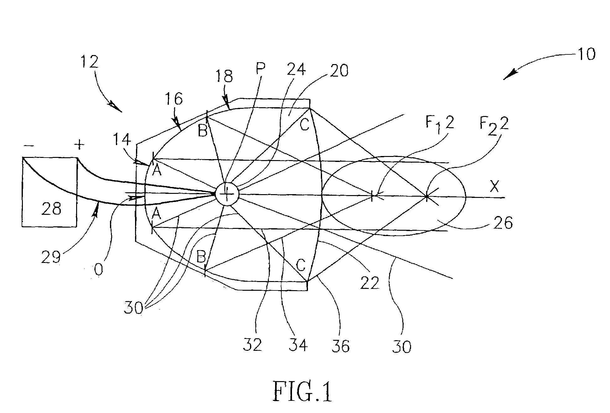
[0194]Reference is now made to FIG. 6, which is a schematic representation of pressure-pulse therapy apparatus 200, in accordance with the present invention. Pressure-pulse therapy apparatus 200 includes a dome-shaped reflector 212 formed of two substantially concentric sections having different curvatures: a substantially parabolic center section 214 having a focal point F at point P, and a substantially ellipsoid ring section 216 having a proximal focal point F1, at point P, and a distal focal point F2. Pressure-pulse source 24 is located on the x-axis, at a point P″, preferably, somewhat closer to reflector 212 than point P. This configuration also provides that a radially expanding primary pulse 30, originating from pressure-pulse source 24 will impinge on reflector 212 and be reflected by it as a compound pressure pulse of somewhat diffused subordinate pulses: a first subordinate pulse 232 which will be slightly convergent, and a poorly focusing second subordinate pulse 234, ge...
fourth embodiment
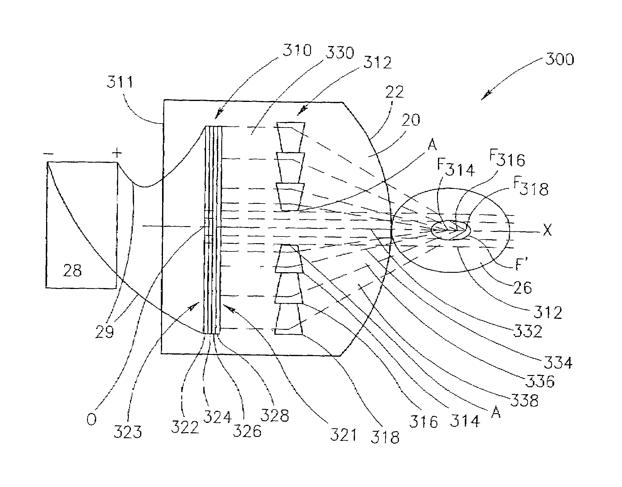
[0201]Reference is now made to FIG. 7, which is a schematic representation of pressure-pulse therapy apparatus 300, in accordance with the present invention. Pressure-pulse apparatus 300 includes an electromagnetic source 310, for example, of a type described in U.S. Pat. No. 4,782,821, to Reitter, incorporated herein by reference. Preferably, electromagnetic source 310 is disk-like, and is formed of the following layers:[0202]i. a disk-like coil 324, having a proximal side 321 and a distal side 323, with respect to region for treatment 26, and connected to power supply 28, via cables 29;[0203]ii. a backing 322, at distal side 323, on which disk-like coil 324 is arranged;[0204]iii. a conductive membrane 328, at proximal side 321; and[0205]iv. an insulating foil 326, arranged between coil 324 and conductive membrane 328.
[0206]Electromagnetic source 310 is thus arranged for generating a collimated pressure pulse 330.
[0207]Preferably, disk-like electromagnetic source 310 is arranged in...
PUM
 Abstract
Description
Claims
Application Information