Carbon nanotubes, process for their production, and catalyst for production of carbon nanotubes

a carbon nanotube and catalyst technology, applied in the direction of carbonsing rags, fibre chemical treatment, coatings, etc., can solve the problems of inability to use each individual carbon tube, inability to control chirality, and fluctuations in the border region of nanotube growth, so as to prevent the growth of carbon nanotubes and achieve high-quality carbon nanotubes. , the effect of reducing the number of carbon nanotubes

Active Publication Date: 2007-12-25
FUJITSU LTD
View PDF3 Cites 47 Cited by
  • Summary
  • Abstract
  • Description
  • Claims
  • Application Information

AI Technical Summary

Benefits of technology

[0016]According to the carbon nanotube production process of the invention, the laminate prepared by alternating lamination of a metal catalyst and a material other than the metal catalyst is cut to expose the laminated structure. The carbon nanotubes are then grown on the metal catalyst at the cut surface of the laminate. By using the cut surface as the growth surface for the carbon nanotubes, bundled growth of carbon nanotubes is prevented and high-quality carbon nanotubes are efficiently produced, each being individually and independently arranged in a highly precise arrangement.

Problems solved by technology

It has been difficult by existing techniques to separate each of the individual carbon nanotubes which have grown in such bundles, and therefore the inability to use each of the individual carbon tubes has been a drawback.
The fluctuation in patterns resulting from lithography has constituted a problem in that it results in fluctuations in the border regions of nanotube growth.
No success has yet been achieved in controlling chirality, and the development of a suitable method is desired.
As explained above, no production process has yet been developed for carbon nanotubes having controlled growth location, diameter, orientation and chirality.

Method used


Image

  • Carbon nanotubes, process for their production, and catalyst for production of carbon nanotubes
  • Carbon nanotubes, process for their production, and catalyst for production of carbon nanotubes
  • Carbon nanotubes, process for their production, and catalyst for production of carbon nanotubes

Examples


example 1

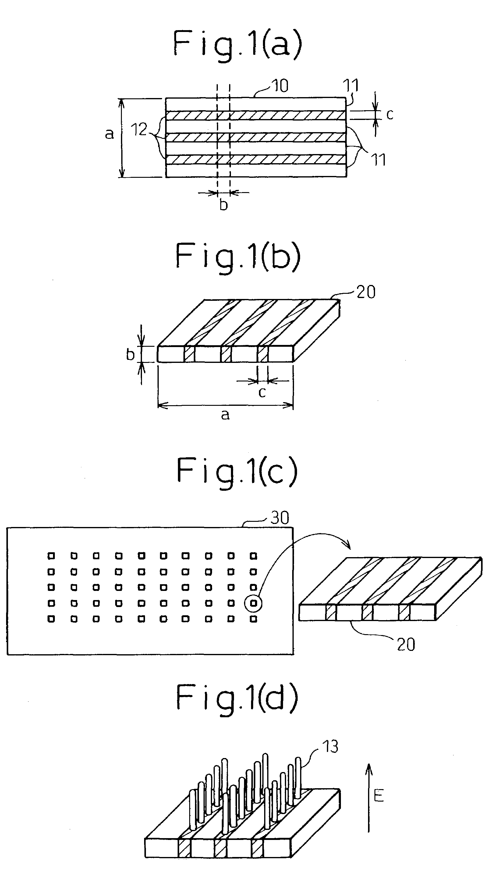
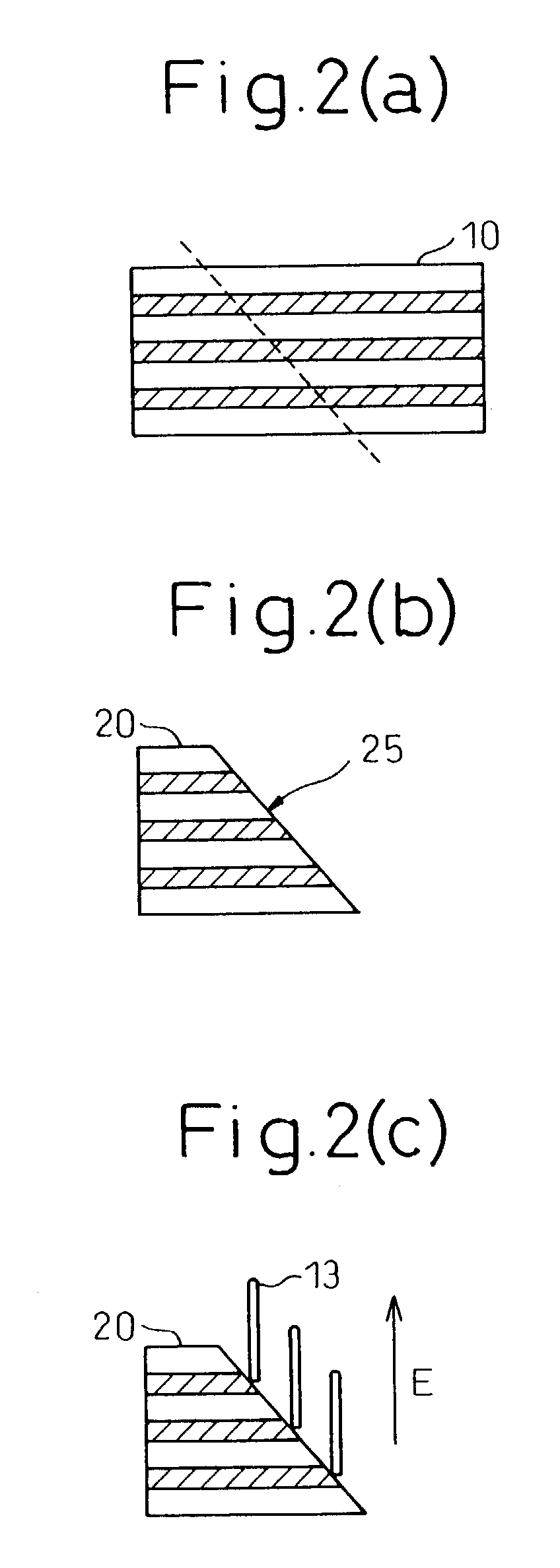
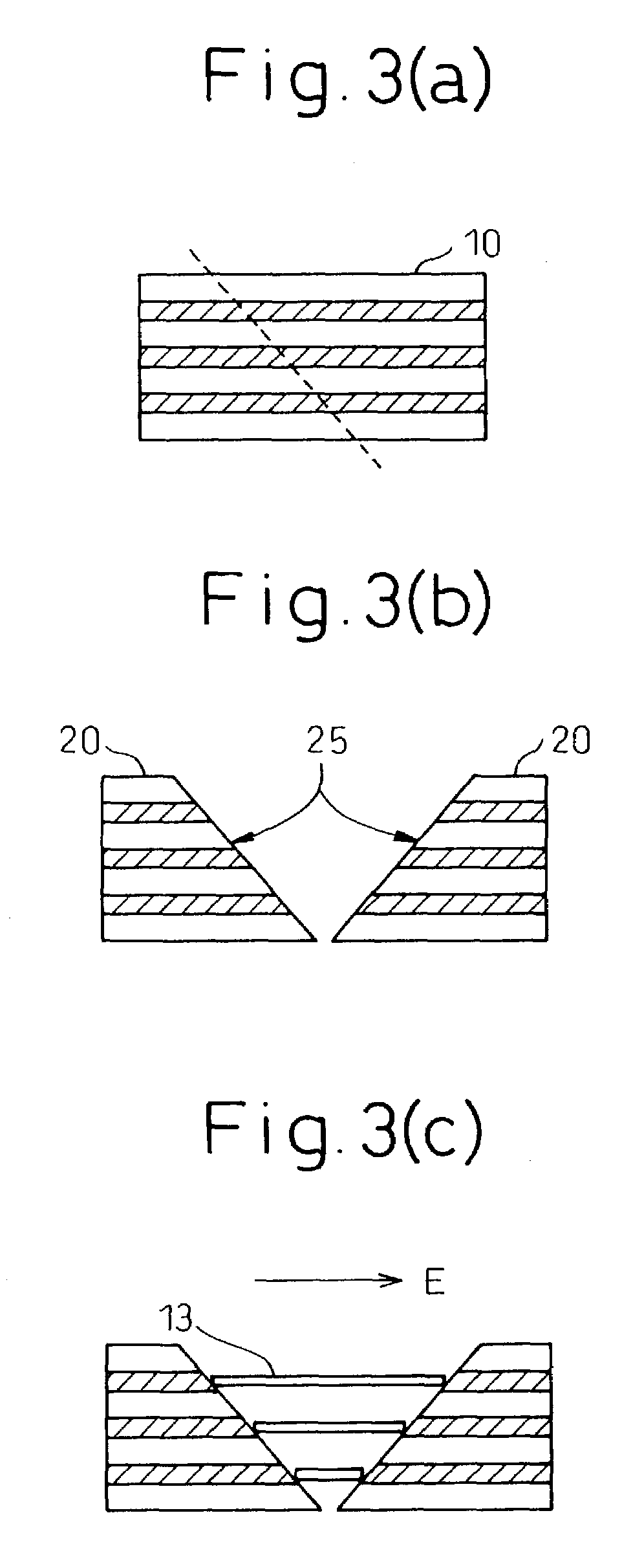
[0090]A carbon nanotube production process according to Example 1 will now be explained with reference to FIG. 1.

[0091]First, a laminate 10 was obtained by alternately forming three layers each of iron and SiO2 on a silicon substrate by vapor deposition. The obtained laminate 10 was cut, by laser cutting, parallel to the direction of lamination of the laminate, to fabricate a one-dimensionally arranged structure 20 (cut piece) of the metal catalyst, having a 1.3 nm width. The obtained one-dimensionally arranged structure 20 was then positioned at a prescribed location on the silicon substrate 30 to expose the cut surface. Using plasma CVD, an electric field was applied in the direction orthogonal to the silicon substrate to grow carbon nanotubes.

[0092]The plasma CVD process was carried out using a plasma CVD apparatus 200 such as shown in FIG. 11, and a 2.45 GHz microwave source 214 as the excitation source, with the silicon substrate 201 situated in the vacuum chamber 202, and unde...


PUM

PropertyMeasurementUnit
diameteraaaaaaaaaa
sizesaaaaaaaaaa
diameteraaaaaaaaaa

Abstract

The invention provides a process for production of carbon nanotubes whereby a laminate prepared by alternating lamination of a metal catalyst and a material other than the metal catalyst is cut to expose the laminated structure, and carbon nanotubes are grown on the metal catalyst at the cut surface of the laminate. The process results in high-quality carbon nanotubes, with minimized bundle growth, which are each individually and independently arranged in a highly precise manner at prescribed locations.The invention also provides a carbon nanotube production process comprising a step of preparing a substrate which is inclined in one or two dimensions from a specific highly symmetrical crystal orientation and vapor depositing a metal catalyst along the atomic steps appearing on the surface of the substrate, and a step of growing the carbon nanotubes by chemical vapor deposition (CVD) using the metal catalyst as nuclei. It is thus possible to control the growth locations, diameters, orientation and chirality of carbon nanotubes.

Description

CROSS-REFERENCE TO RELATED APPLICATIONS[0001]This application is based upon and claims priority of Japanese Patent Applications Nos. 2002-178451 and 2002-235015 filed on Jun. 19, 2002 and Aug. 12, 2002, respectively, the contents being incorporated herein by reference.BACKGROUND OF THE INVENTION[0002]1. Field of the Invention[0003]The present invention relates to a process for highly efficient production of carbon nanotubes with limited bundle growth and a highly precise arrangement, to high-quality carbon nanotubes, produced by said process, which are each individually and independently arranged in a highly precise manner at prescribed locations, and to a carbon nanotube production catalyst which is suitable for production of said carbon nanotubes.[0004]The present invention also relates to a process for the production of carbon nanotubes on a substrate which is inclined from a highly symmetrical crystal orientation, or an “off-substrate”.[0005]2. Description of the Related Art[000...

Claims


Application Information

Patent Timeline
Patent Type & Authority Patents(United States)
IPC IPC(8): D01F9/12
CPCB82Y30/00D01F9/12D01F9/1272D01F9/133D01F9/127Y10S977/843
Inventor AWANO, YUJIYAMAGUCHI, YOSHITAKAARINAGA, KENJIFUJITA, SHOZO
Owner FUJITSU LTD
Why Eureka
Try Eureka