Powered panel moving system

a technology of moving system and power panel, which is applied in the direction of program control, dynamo-electric converter control, instruments, etc., can solve the problems of increased speed and torque, disadvantage of requiring additional speed and/or window position sensors, and higher speed and torque, so as to achieve the effect of reducing the cost of brush-less electronics and mechanical advantages

Inactive Publication Date: 2007-12-25
UUSI
View PDF108 Cites 36 Cited by
  • Summary
  • Abstract
  • Description
  • Claims
  • Application Information

AI Technical Summary

Benefits of technology

[0019]It is still another object of the present invention to provide a powered panel moving system having a small, high-speed motor configured with a higher mechanical advantage than used with a larger, low-speed motor such that cost savings from the resulting reduction in motor materials accommodates the cost of brush-less electronics used for the small, high-speed motor.
[0021]In carrying out the above objects and other objects, the present invention provides a powered panel moving system for moving a panel. The system includes a motor, electronic drive means, mechanical means, coupling means, and electronic function means which may all be located within a housing. The electronic drive means drives the motor in order to rotate a rotor of the motor. The rotor has a rotational output in response to being driven. The mechanical means moves a panel upon being driven. The coupling means couples the rotational output of the rotor to the mechanical means in order drive the mechanical means for the mechanical means to move the panel. The electronic function means is integrated with the electronic drive means for providing additional functionality beyond driving the motor for movement of the panel.
[0032]The advantages associated with the powered panel moving system in accordance with the present invention are numerous. For instance, the powered panel moving system is cost competitive to existing low cost powered panel moving systems while providing improved obstruction detection capability of more expensive powered panel moving systems.

Problems solved by technology

Unfortunately, a force having a magnitude of more than 100 N is sufficient to cause injury when a human body part become entrapped in a window being closed by this force.
This has the disadvantage of requiring the sensor.
This has the disadvantage of requiring additional speed and / or window position sensors.
However, a smaller DC motor can have approximately the same rated power as a larger DC motor for approximately the same input voltage and current, but will have it at a higher speed and lower torque.
This can result in higher temperature operation for a smaller motor running at the same drive voltage and power of a larger motor.
However, many DC applications such as automotive applications have limitations in drive voltage.
This can limit the power rating of the motor as the armature can dissipate heat from the load current only through its shaft and bearings and heat rejection to air inside the motor case.
However, the design choice of a smaller motor has disadvantages.
The first design challenge is that higher speed operation reduces the useful life of any brushes that are used.
The second design challenge is that a more extreme “gear reduction” / “mechanical advantage” ratio is required to recover the equivalent torque that would be obtained from a larger motor at the same power rating.
This could cause more wear and acoustic emissions than experienced with the lower gear ratio operating at lower motor speed.
The third design challenge is that human hearing sensitivity is lower at the 50 Hz of a 3,000 rpm motor than at the 500 Hz of a 30,000 pm motor, resulting in the higher speed motor presenting a higher audio profile than would a larger, slower motor.
The fourth design challenge is in matching the motor to the mechanical coupling means used to match the motor's mechanical output to whatever component the motor is intended to move, e.g., an automotive power window or panel.
However, this introduces more cost via the additional electronics required for brush-less operation.

Method used


Image

  • Powered panel moving system
  • Powered panel moving system
  • Powered panel moving system

Examples


Embodiment Construction

)

[0045]In high duty cycle applications, the requirement to dissipate heat can lead to the use of a larger motor running at a lower speed than would otherwise be desired. In such a case it could be advantageous to use an external armature for improved heat dissipation to allow operation with a smaller motor in order to realize lower motor material cost, weight, and volume. However, this change requires the use of brush-less electronics which impose an increased cost although brush-less designs are more reliable by eliminating brush wear and failure.

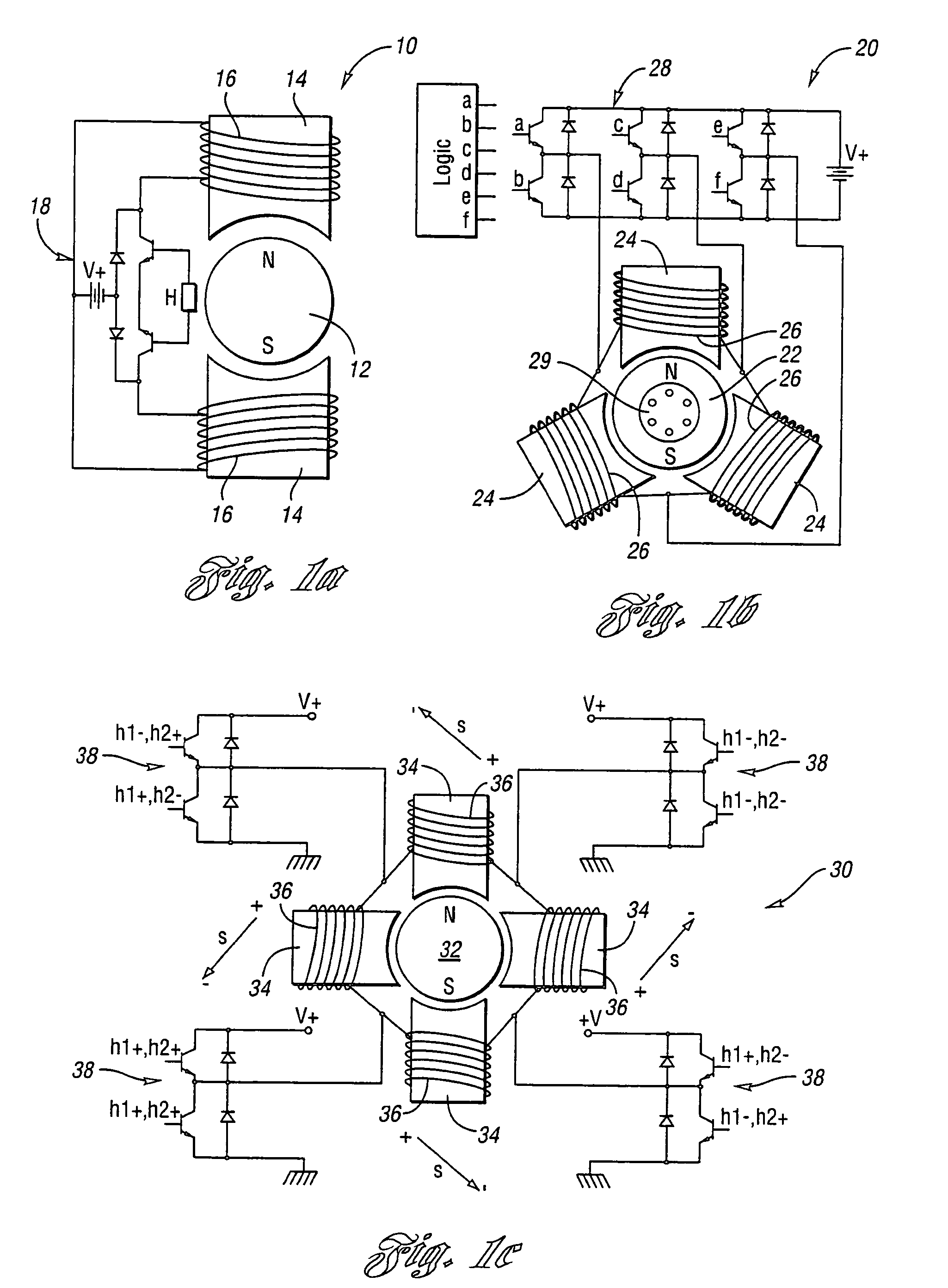
[0046]Among other variations, brush-less motor electronics are provided in two, three, and four phase variants with unipolar and bipolar excitations. FIGS. 1a, 1b, and 1c respectively illustrate representative mechanical and electrical configurations of two, three, and four phase sensor-based brush-less motors.

[0047]FIG. 1a illustrates a mechanical and electrical configuration of a two-phase sensor-based brush-less motor 10. Motor 10 inclu...


PUM


Abstract

A powered panel moving system includes a motor, electronic drive circuitry, a mechanism, a coupler, and electronic function circuitry. The drive circuitry drives a rotor of the motor. The coupler couples rotational output of the rotor to the mechanism to drive the mechanism in order to move the panel. The function circuitry is integrated with the drive circuitry for providing additional functionality beyond driving the motor for panel movement. The drive circuitry includes a current sensor for determining rotor position based on motor current, a back emf sensor for determining rotor position based on back emf of the motor, and an impedance sensor for determining rotor position based on motor impedance. The function circuitry may include an analyzer to determine presence of an obstruction to the motion of the panel based on at least one of the rotor position, the motor current, and the back emf of the motor.

Description

BACKGROUND OF THE INVENTION[0001]1. Field of the Invention[0002]The present invention generally relates to powered panel moving systems and, more particularly, to a powered panel moving system having electronic function circuitry integrated with electronic motor drive circuitry for providing additional functionality beyond driving a motor for movement of a panel.[0003]2. Background Art[0004]Standard automotive power window systems employ a brush type direct current (DC) motor with reduction gearing and suitable rotary-to-linear motion transformation fixtures to enable the motor to raise and lower a window. The requirement to drive the window completely into a compressible weather seal upon closing and withdraw the window upon opening can lead to forces driving the window having a magnitude of many Newtons (N).[0005]Suitable fixtures for converting motor torque into the required closure force include cable systems, worm gears, planetary gears, and rack and pinion gearing systems, and...

Claims


Application Information

Patent Timeline
Patent Type & Authority Patents(United States)
IPC IPC(8): H02P7/00
CPCE05F15/697H02H7/0851E05F15/41E05Y2400/554E05Y2900/55G05B2219/37317G05B2219/45242H02H3/05H02H1/0007
Inventor WASHELESKI, JOHN M.COOPER, STEPHEN R. W.STROM, PETER H.NEWMAN, TODD R.
Owner UUSI
Why Eureka
Try Eureka