System and method for optically detecting a click event

a click event and optical detection technology, applied in the field of image acquisition, can solve the problem that the space provided for a separate selection button on the surface of the electronic device may not be acceptable, and achieve the effect of reducing size and cos

Active Publication Date: 2007-12-25
PIXART IMAGING INC
View PDF19 Cites 86 Cited by
  • Summary
  • Abstract
  • Description
  • Claims
  • Application Information

AI Technical Summary

Benefits of technology

[0011]Using an optical mechanism to detect click events reduces the size and cost for implementing application selection capabilities on an electronic device. Furthermore, the invention provides embodiments with other features and advantages in addition to or in lieu of those discussed above. Many of these features and advantages are apparent from the description below with reference to the following drawings.

Problems solved by technology

However, the optical mice available on the market today still require the use of buttons or other electromechanical selection devices to access applications provided by the associated electronic devices.
With the increasing trend towards miniaturization in the design of cell phones, laptop computers, personal digital assistants, electronic mice and other electronic devices, providing the space for a separate selection button on the surface of the electronic device may not be acceptable.

Method used


Image

  • System and method for optically detecting a click event
  • System and method for optically detecting a click event
  • System and method for optically detecting a click event

Examples


Embodiment Construction

[0024]The numerous innovative teachings of the present application will be described with particular reference to exemplary embodiments. However, it should be understood that these embodiments provide only a few examples of the many advantageous uses of the innovative teachings herein. In general, statements made in the specification do not necessarily delimit any of the various claimed inventions. Moreover, some statements may apply to some inventive features, but not to others.

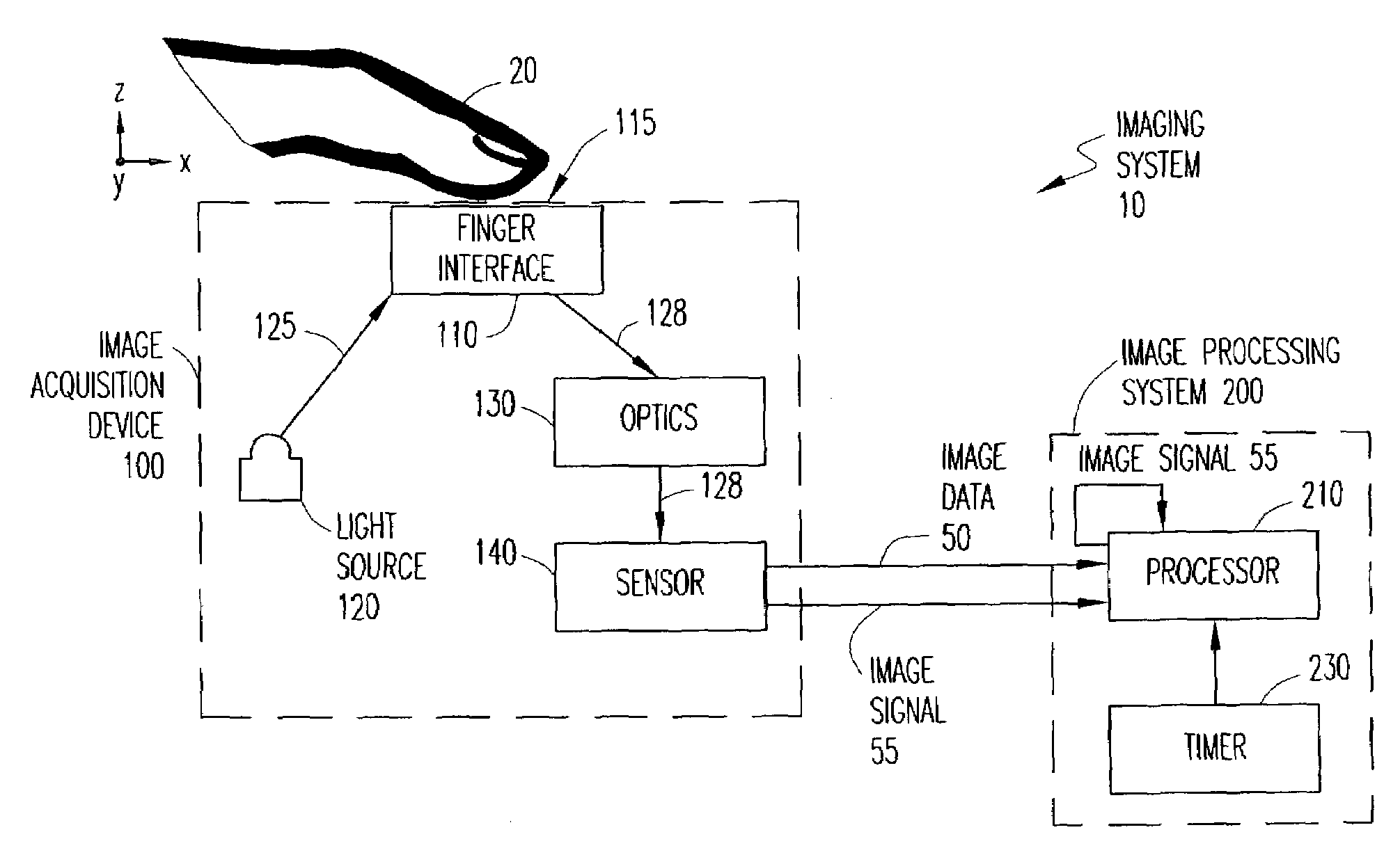
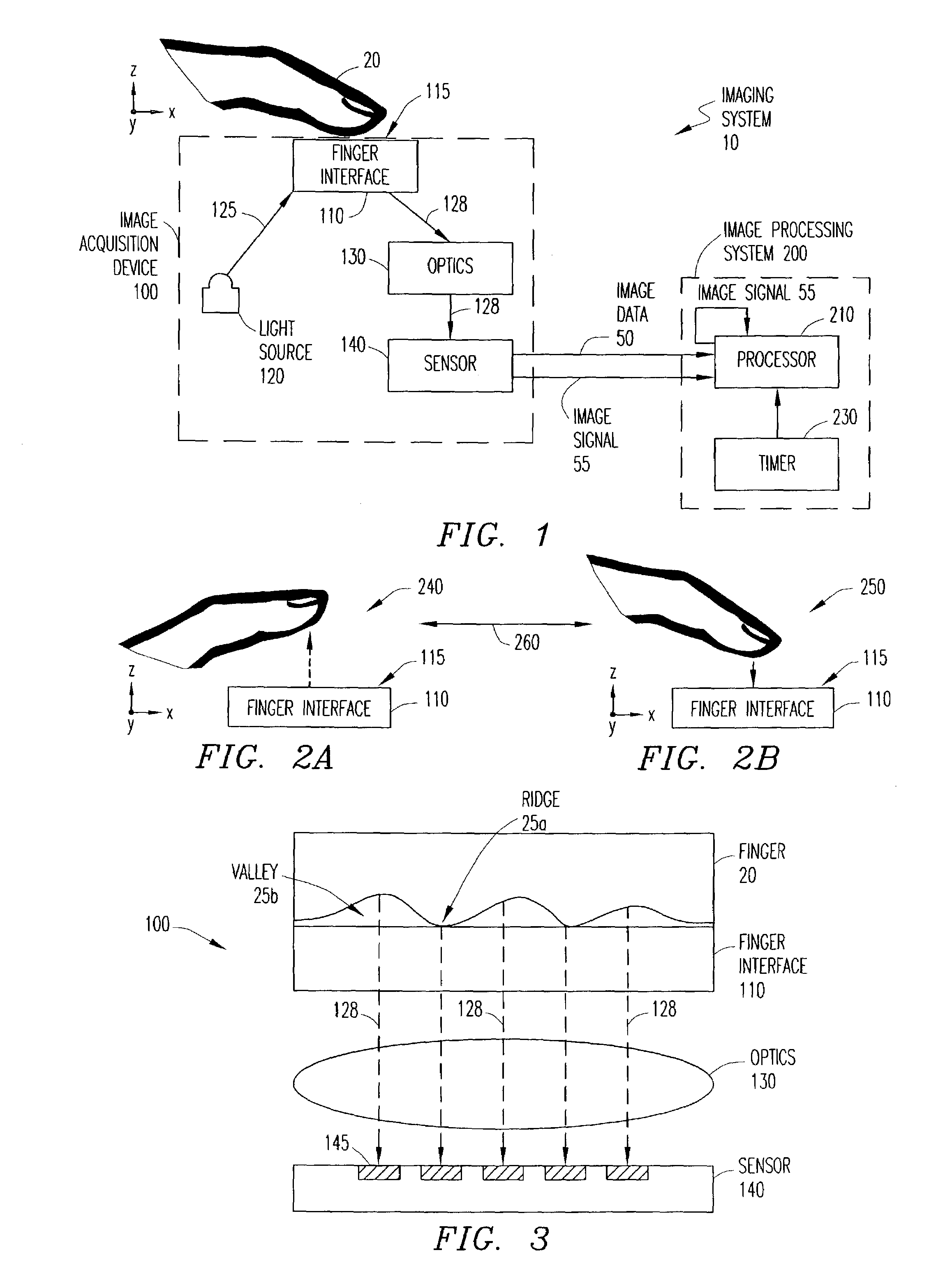
[0025]FIG. 1 illustrates an exemplary imaging system 10 that can be used with the present invention to detect a finger click motion, which will be described in more detail below in connection with FIGS. 2A and 2B. For example, a finger click motion can be a finger lift-up motion or a finger put-down motion. Combinations of finger click motions can be detected to indicate a click event, such as a single click, double click, triple click or any other multiple click. A click event is analogous to the operation ...


PUM


Abstract

An imaging system captures a sequence of images representing finger lift-up and finger put-down motions over a sensing area and produces an image signal for use in detecting a click event. At least one light source illuminates a finger interface upon which a user places a finger (or thumb). Light reflected from the finger is captured by an image sensor as image data corresponding to the sequence of images. At least one image signal is produced in connection with or based on the image data. The image signal is used to detect a finger lift-up or finger put-down motion. A click, such as a single click, double click or triple click, is detected based on a combination of finger lift-up and finger put-down motions within a configurable time range.

Description

BACKGROUND OF THE INVENTION[0001]1. Technical Field of the Invention[0002]The present invention relates generally to the field of image acquisition. More specifically, the present invention relates to systems and methods for obtaining and processing images of fingerprints for click detection purposes.[0003]2. Description of Related Art[0004]Many electronic devices, such as personal computers, laptop computers, wireless telephones and personal digital assistants (PDAs), provide a navigation mechanism for controlling a cursor or pointer on a screen. By far, the most popular navigation mechanism in PC usage is the mouse. Recently, optical mice have been developed that are able to navigate on nearly any arbitrary surface using a tracking algorithm that correlates sequential images in the direction of movement.[0005]For example, U.S. Pat. No. 6,281,882, entitled PROXIMITY DETECTOR FOR A SEEING EYE MOUSE, which is hereby incorporated by reference in its entirety, describes an optical mous...

Claims


Application Information

Patent Timeline
Patent Type & Authority Patents(United States)
IPC IPC(8): G06K9/00G06F3/033G06M7/00G06T1/00G06K9/22G06T5/50
CPCG06F3/03547G06K9/222G06F2203/0338G06V30/1423G06F3/033G06F3/042G06F3/0421
Inventor MACHIDA, AKIHIROBAHARAV, IZHAK
Owner PIXART IMAGING INC
Why Eureka
Try Eureka