Cutter bar

a technology of cutter bars and guide plates, applied in the field of cutter bars, can solve the problems of increased cutting force, friction between the knife and the guide plate, and large wear on the knife bar and the guide plate, and achieve the effect of long li

Active Publication Date: 2008-01-01
SCHUMACHER GUSTAV
View PDF9 Cites 33 Cited by
  • Summary
  • Abstract
  • Description
  • Claims
  • Application Information

AI Technical Summary

Benefits of technology

[0006]It is the object of the present invention to provide a cutter bar which has a long life. The present invention enables an adaptation of the support for the knife.
[0008]Accordingly, no frictional resistance between the knife and the finger bar has to be overcome. Only the rolling resistance of the rollers has to be overcome, which is distinctly lower. Thus, distinctly lower driving forces are necessary to drive the knife. Thus, smaller dimensioned drives can be used.
[0009]Due to the use of a roller holder, no specific fixing bores need to be provided to attach the rollers. Rather, the roller holder can be adapted to different cutter bars from different manufacturers. Furthermore, it is possible to retrofit existing cutter bars. A further advantage is that it is possible to adjust the roller holder in its position with respect to the finger bar.
[0013]Accordingly, the knife is vertically supported. For better self-cleaning of penetrated soil material, neighbouring rollers can, alternatively, be provided, respectively, with one first collar or one second collar. Here, one roller has only one first collar, wherein the next neighbouring roller has only one second collar.
[0014]The rollers can be rotationally supported on the finger bar around a vertically arranged rotational axis. Accordingly, the rollers can have a bearing bore which extends coaxially to the rotational axis. Thus, the rollers are rotationally supported on an outer face of a bearing shaft and form a sliding-type bearing. This represents an extremely low cost and robust bearing arrangement. The rollers and the bearing shafts can be manufactured from a hard-sintered material. Also, rolling member bearings can be provided between the rollers and the corresponding bearing shafts.

Problems solved by technology

The cutting force can increase due to the harvesting good, which is difficult to cut, or due to dull knife blades.
This leads, especially with sandy and corundum-containing soil, to a larger wear on the knife bar and on the guide plate.
However, friction is still produced between the knife and the guide plates.

Method used


Image

  • Cutter bar
  • Cutter bar
  • Cutter bar

Examples


first embodiment

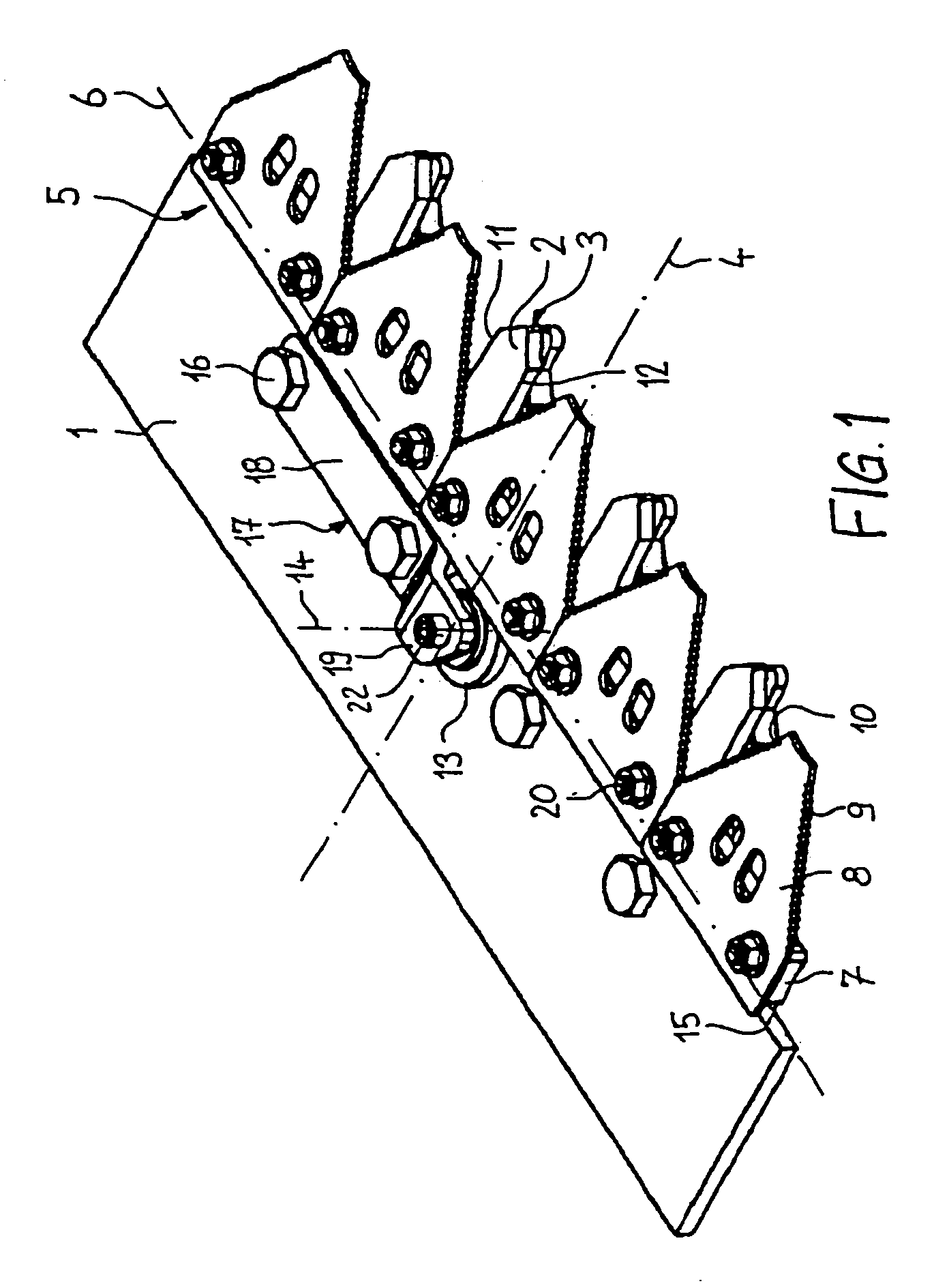
[0028]FIG. 1 illustrates a cutter bar according to the invention. The cutter bar has a finger bar 1, attached on an agricultural implement. Reaping fingers 2 are arranged on the cutter bar 1. The free ends 3 of the reaping fingers 2 point in the working direction of the agricultural implement and are arranged parallel to a longitudinal axis 4. A knife 5 is reciprocatingly movably guided along a transverse axis 6 relative to the finger bar 1. The transverse axis 6 extends at a right angle to the longitudinal axis 4. The knife 5 includes a knife bar 7 as well as several blades 8. The blades 8 are supported on each other in the direction of the transverse axis 6. The blades 8 form, respectively, a first cutting edge 9 and a second cutting edge 10. The first cutting edges 9 interact, respectively, with at least one first counter cutting edge 11 of a reaping finger 2. The second cutting edges 10 also interact, respectively, with at least one second counter cutting edge 12 of the reaping ...

second embodiment

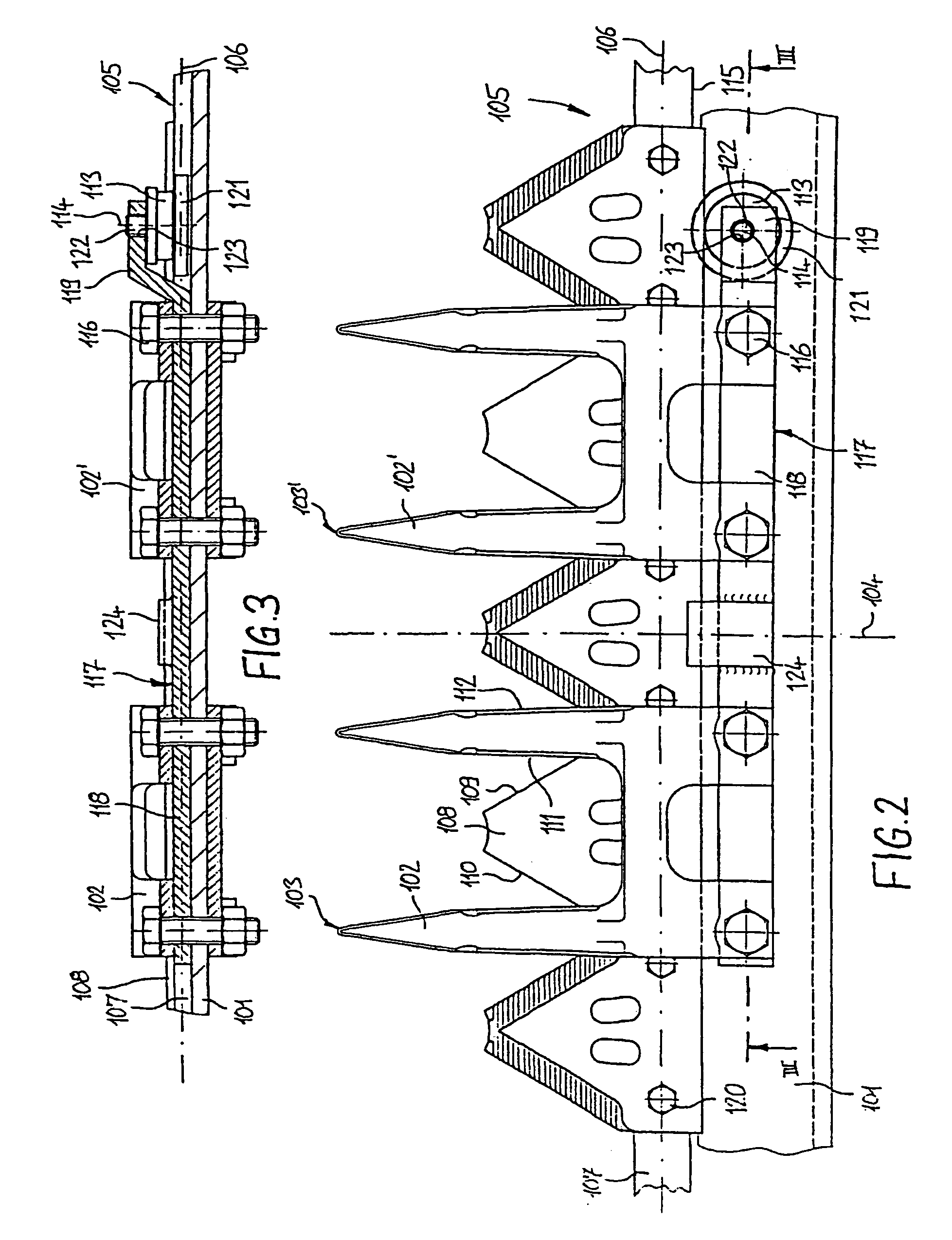
[0037]Unlike the second embodiment, the roller holder 217 is formed shorter and is attached by a fixing screw 216 to one of the reaping fingers 202 on the top of the reaping finger 202.

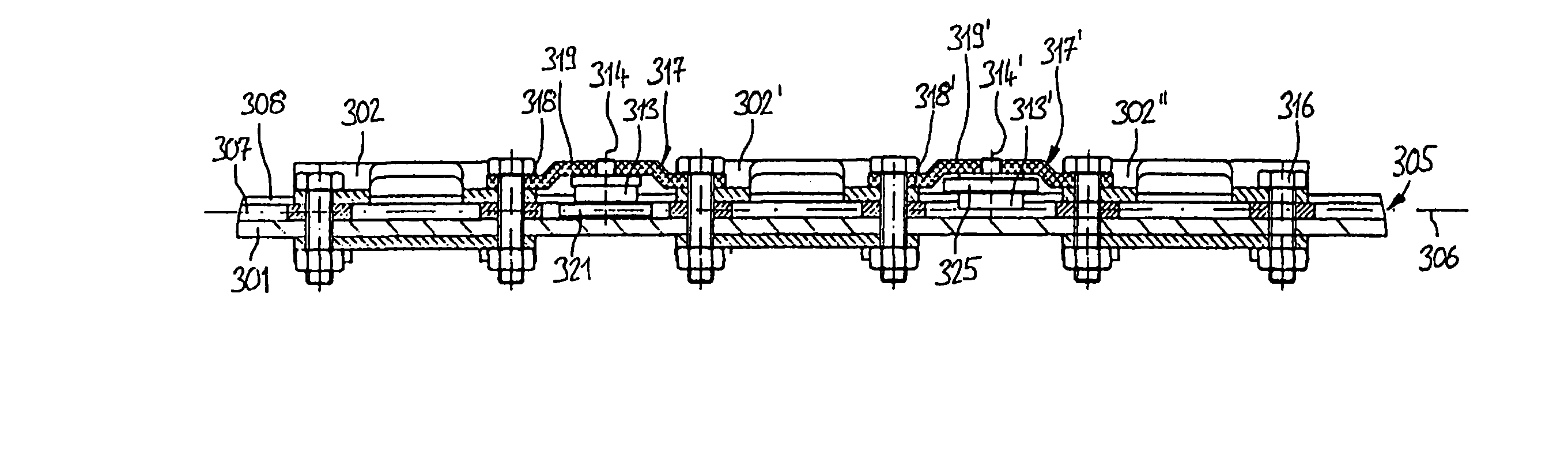
[0038]A fourth embodiment is illustrated in FIGS. 6 and 7. Components, which correspond to components of the first embodiment, are provided with reference numerals, which are increased by the numerical value 300.

fourth embodiment

[0039]In the fourth embodiment, the roller holders 317 are in the form of bridges. The roller holders 317 are arranged between neighbouring reaping fingers 302, 302′, 302″. The roller holders 317 are fixed by fixing screws 316 of the neighbouring reaping fingers 302, 302′, 302″.

[0040]Furthermore, one of the rollers has a first collar 321. The blades 308 are supported vertically downwards against the first collar 321. A roller 313′, arranged next to the roller 313, has a second collar 325. The blades 308 are vertically supported upwards against the second collar 325. Thus, this ensures an improved guide of the knife 305.

[0041]Alternatively, all rollers can have, respectively, a first collar and a second collar. Thus, the blades are supported vertically downwards as well as vertically upwards on each roller. Further, the reaping fingers can be arranged vertically below the finger bar. Also, the roller holders can be arranged vertically below the reaping finger.


PUM


Abstract

The invention relates to a reciprocating cutting bar for the cutting gear of an agricultural machine, comprising a longitudinal axis (4) along which the reciprocating cutting bar may be moved in a working direction for crop cutting, a finger bar (1), cutting fingers (2), which are fixed to the finger bar (1), each forming counter cutters (11), a knife (5) with a knife bar (7), having knife blades (8) fixed to the knife bar (7) which each have cutters (9), whereby the knife (5) is made to oscillate relative to the finger bar (1) along a transverse axis (6), which is arranged horizontally and perpendicular to the longitudinal axis (4), rollers (13), by means of which the knife (5) is supported against the finger bar (1) to the rear when viewed in the working direction. The rollers (13) are each mounted to rotate on a roller holder (17) and the roller holders (17) are fixed to the finger bar (1).

Description

CROSS-REFERENCE TO RELATED APPLICATIONS[0001]This application claims priority to German Patent Application No. 10246867.2, filed Oct. 8, 2002, which application is herein expressly incorporated by reference.FIELD OF THE INVENTION[0002]The invention relates to a cutter bar of a cutting device of an agricultural implement.BACKGROUND OF THE INVENTION[0003]Cutter bars include a finger bar which has a plurality of reaping fingers. A knife reciprocates relative to the finger bar. The knife includes a knife bar which has several blades. The blades form cutting edges. Counter cutting edges are formed by the reaping fingers and interact with the blades.[0004]The blades have a generally triangular base. During the cutting procedure, the harvesting goods, due to the reciprocating movement of the knife, are pressed by the blades against the reaping fingers and cut. Accordingly, a scissor-like cutting movement is produced. Thus, each individual blade is pushed to the back, when viewed in a worki...

Claims


Application Information

Patent Timeline
Patent Type & Authority Patents(United States)
IPC IPC(8): A01D34/40A01D34/16
CPCA01D34/16
Inventor SCHUMACHER, GUSTAVSCHUMACHER, FRIEDRICH-WILHELM
Owner SCHUMACHER GUSTAV
Why Eureka
Try Eureka