
Method and system for determining the position of marine vessels and similar objects

Active Publication Date: 2008-01-01
KONGSBERG MARITIME
View PDF14 Cites 25 Cited by
  • Summary
  • Abstract
  • Description
  • Claims
  • Application Information

AI Technical Summary

Benefits of technology

[0016]An object is to create measurements “blind” to objects other than the identifiable transponders to be measured relative to, and thereby make a more reliable positioning system than prior art systems do.
[0019]The system has to meet the demands for high reliability and low maintenance cost.
[0023]The modulated signal from the transponder solves three different issues. The signals are unique for each transponder, making it possible to distinguish between the different transponders used in the system. The signal modulated by the transponders relocates the reflected radar signal, making it possible to exclude all “clutter” conventional radars have to allow for. The removal of all other reflections from the signal makes it possible to utilise several receiving antenna elements to compare the phase front of the received signal to measure the angle to the transponder, without utilising a rotating antenna.
[0027]This provides a method for positioning, which is suitable for several fields of utilisation. The transponders may, due to the construction of the interrogator, be of a simple design, making the cost of production low. The system is suitable for utilisation by several users, for example multiple supply vessels simultaneously.

Problems solved by technology

However, this may be extremely difficult far out at sea, where huge waves and high wind affect the movement of the vessel.
This may lead to damage on the vessel, the platform, and the crew, and also cause leakage of oil and gas, which leads to pollution, and the danger of explosion.
The laser based systems have severe limitations, i.e. tracking of false targets (reflectors), reduced accuracy and loss of signal due to sunlight saturation as well as absorption and loss of signal due to snow, heavy rain or fog in the path of the laser light.
Another severe limitation is low reliability due to movable parts (motor and gearbox) driving the scanning lasers.
However, it can be vulnerable to degraded satellite constellation, specifically if the vessel is near a large structure that is blocking the view of the horizon.Radar based systems, e.g. “Artemis” (trademark) from CHL NETHERLANDS B.V. and “RadaScan” (trademark) from GCS (Guidance Control Systems), UKThese systems utilise a conventional rotating radar antenna both on the vessel and at the remote station.
This system can only track one target, and can only be used by one vessel at a time.
It is expensive, and reliability is an issue due to the engine controlled antennas.

Method used


Image

  • Method and system for determining the position of marine vessels and similar objects
  • Method and system for determining the position of marine vessels and similar objects
  • Method and system for determining the position of marine vessels and similar objects

Examples


Embodiment Construction

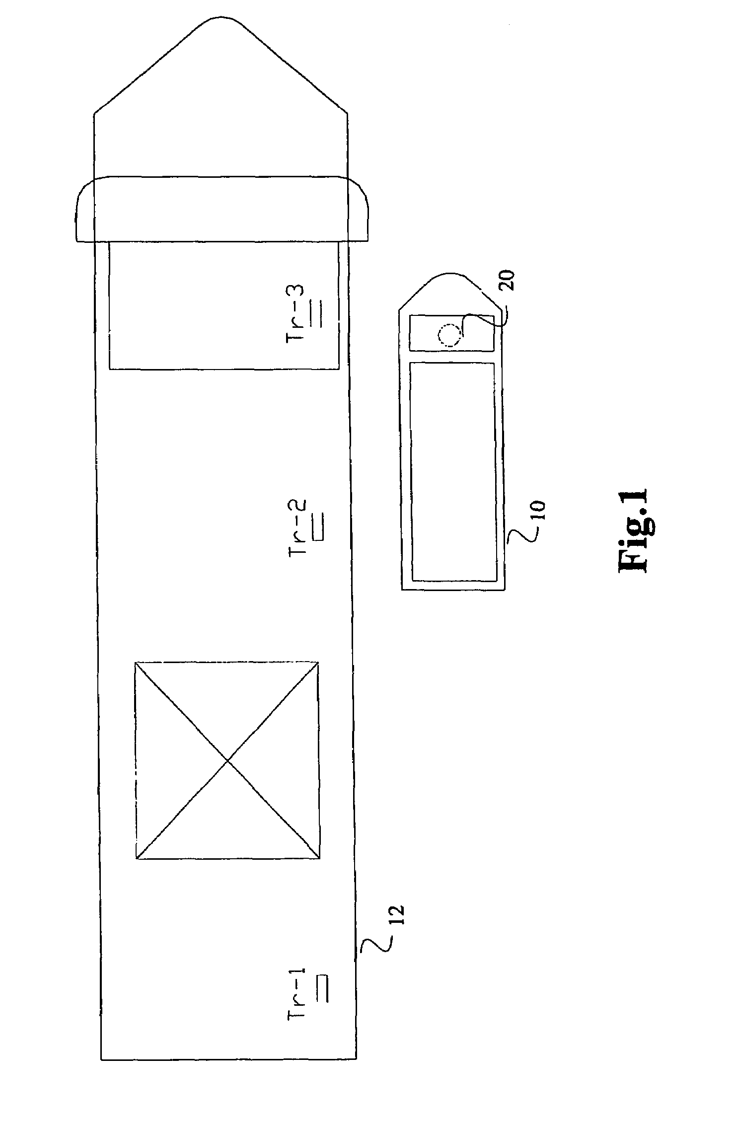
[0034]In FIG. 1 the present invention is used for positioning a supply vessel 10 next to an oil drilling platform 12. The supply vessel is provided with an interrogator 20, which will be described in more detail later. The platform 12 is a floating production vessel, which has three transponders TR-1, TR-2 and TR-3 arranged along the docking side for the supply vessels 10.

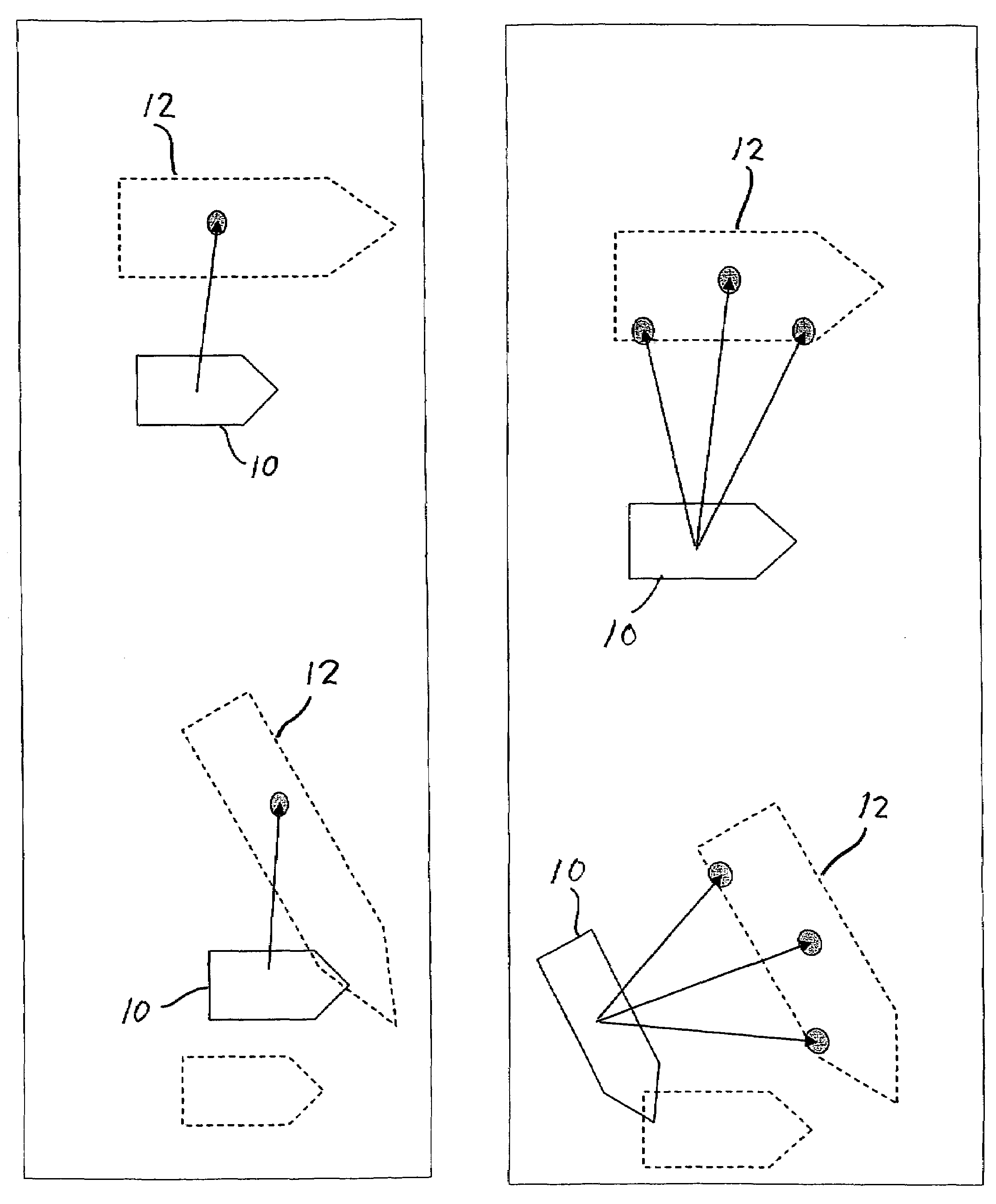
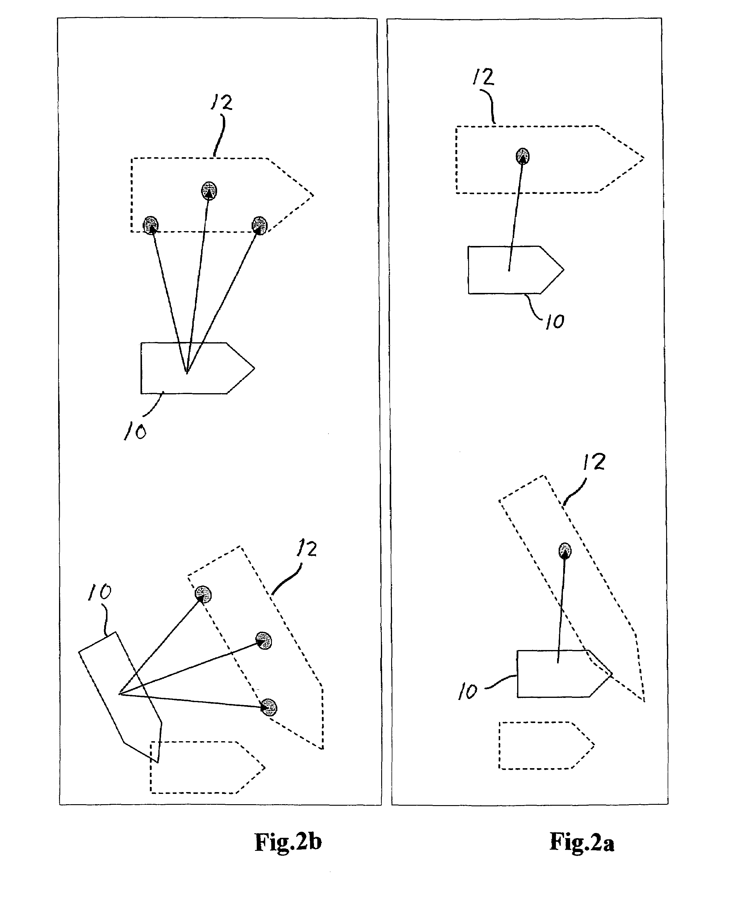
[0035]In FIG. 2a the docking of a supply vessel 10 with a system with one transponder Tr is shown. The Figure illustrates a collision with the production vessel 12, which potentially may occur. FIG. 2b illustrates the capability of correct tracking of the remote production vessels movement, and moves automatically with it, when multiple transponders Tr1 and Tr2 are utilised for positioning.

[0036]FIG. 3 illustrates a particular use of the system according to the invention, comprising an interrogator 20 arranged on a seismic vessel 10, and transponders Tr arranged on floats 13 and dragged behind the vessel 10. In thi...


PUM


Abstract

A method for determining the relative position between two or more objects in a marine environment, including waterways, of which at least one object can be maneuvered relative to one or more other objects. At least one interrogator is arranged on one or more of the objects and sends a radio wave signal to at least one transponder arranged on one or more of the other objects. The novel method is the use of a FMCW radar in the interrogator, the use of the transponders for including identity tags into the signals to be reflected to the interrogator, and attitude determination. A system for this determination is also described.

Description

[0001]This application is a filing under 35 USC 371 of PCT / NO2005 / 000091 filed Mar. 15, 2005.[0002]The present invention relates to a method, for determining the position, especially for a marine vessel in relation to other vessels or installations, by use of radar frequency signals. It also relates to a system for such determination.BACKGROUND OF THE INVENTION[0003]In connection with the offshore petroleum industry, it is often required to position a vessel in immediate proximity to a harbour, a platform or similar, to be able to carry out loading and unloading of goods, and to load oil and gas onto large vessels etc. However, this may be extremely difficult far out at sea, where huge waves and high wind affect the movement of the vessel. Some platforms also float in such a way that both the vessel and the platform move independently of each other. In the North Sea, a series of cases has been reported, wherein vessels have hit an adjacent platform. This may lead to damage on the ve...

Claims


Application Information

Patent Timeline
IPC IPC(8): G01S7/40G01S13/82G01S13/93G01S13/87
CPCG01S13/82G01S7/4056G01S13/876G01S2007/4091G01S7/4091
Inventor FOSSUM, BJORN
Owner KONGSBERG MARITIME
Features
  • Generate Ideas
  • Intellectual Property
  • Life Sciences
  • Materials
  • Tech Scout
  • Unparalleled Data Quality
  • Higher Quality Content
  • 60% Fewer Hallucinations
Learn More