Button lock

a button-operated lock and button technology, applied in the direction of mechanical control devices, keyhole guards, instruments, etc., can solve the problems of large size and heavy weight of the entire button-operated lock, unobtainable enough safety performance, and insufficient setting amount of information, so as to achieve enhanced safety performance, wide selection range, and reduced number of control buttons

Inactive Publication Date: 2008-01-08
NAGASAWA SEISAKUSHO
View PDF17 Cites 19 Cited by
  • Summary
  • Abstract
  • Description
  • Claims
  • Application Information

AI Technical Summary

Benefits of technology

[0022]A button-operated lock according to the present invention comprises a plurality of control buttons axially displacedly arranged and capable of setting or inputting a predetermined information; a control plate for allowing an unlocking procedure at the time of setting or imputing the predetermined information; a driving cam linked to the control plate and capable of being operatively connected to a pair of door handles; and a lock element linked to the driving cam, wherein a plurality of same or different information can be set or inputted to each of the control buttons and the plurality of same or different information can be set or inputted every time the control button is operated. Accordingly, a large number of combination of password numbers can be obtained compared with the conventional technique in which only one memory information is set or inputted to a plurality of control buttons and plural sorts of password numbers are obtained by changing the combinations of the control buttons. Since the range of selection can be widened, the safety performance can be enhanced and the number of the control buttons can be reduced to that extent. Moreover, no reset button is required contrary to the conventional technique. Thus, the number of component parts can be reduced and the structure can be simplified. In addition, the device according to the present invention can be manufactured easily and economically.
[0023]Accordingly, the case, etc. can be made short and small, and reduced in width by an amount equal to the reduction of the number of control buttons. Thus, the invented device can be made compact and light weight, and the appearances of the button-operated lock and the door can be improved. Moreover, the backset dimensions from the side end face of the door to the center of the lock can be made compact and thus, this lock can be suited to be used for a kitchen door.
[0024]Moreover, in the button-operated lock, plural sorts of memory information can be set or inputted in accordance with the number of times of depressing operation of the control buttons. Accordingly, there is no worry for being perceived the memory information from the finger prints printed on the surfaces of the control buttons and the wearing condition of the surfaces of the control buttons when compared with the conventional technique in which only one memory information is set or inputted to a plurality of control buttons. Thus, the safety performance can be enhanced.

Problems solved by technology

However, in this conventional device, since only two modes, i.e., number setting and number unsetting, can be obtained for each control button and the setting amount of information for each control button is limited, the number of the password number depends on the number of the control buttons and thus, a sufficient setting amount of information is unobtainable.
Since the range of selection thereof is limited, a large enough safety performance is unobtainable.
Thus, the construction and the locking and unlocking procedure becomes complicated, and the case frame and the packing plate become large in size, thus resulting in large size and heavy weight of the entire button-operated lock.
Moreover, the outer appearance of the door is degraded.
However, the lock taught by the above U.S. patent has the following problems.
Since each control button can set only a single memory information, a combination of memory information achievable through each control button is limited, and selection of password numbers and safety performance are limited.
Moreover, since the number setting of the control buttons is linked to the number setting of the adjacent control buttons and the password number is stored in order of the setting input, the number setting lacks in versatility and the smooth execution of the locking and unlocking procedure is jeopardized.
This, together with the above-mentioned disadvantage in limitation of the memory capacity, tends to create such a fear that repeated evil attempt should be made on the control buttons, the lock could be unlocked comparatively easily.
On the other hand, a long time use of a same password number leads gives a chance to a third party to perceive and decode the number.
However, since the alternation mechanism and operation thereof requires a time-consuming troublesome work in view of its structure, the simplification and easiness are demanded.
However, this method has such problems that since the case frame and the backing plate are required to be detached from the door and the buttons are required to be detached or replaced, complicated and time-consuming work is required.
However, it has such a problem that since the password number can be altered from the outside of the door, the third party can make a falsification relatively easily.
Therefore, uneasiness in relation to protection and security occurs.

Method used


Image

  • Button lock
  • Button lock
  • Button lock

Examples


Embodiment Construction

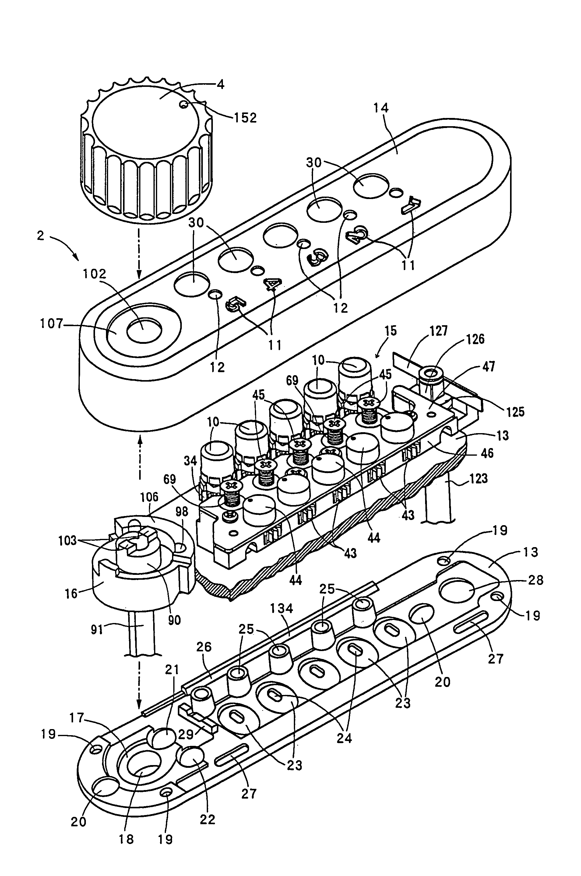
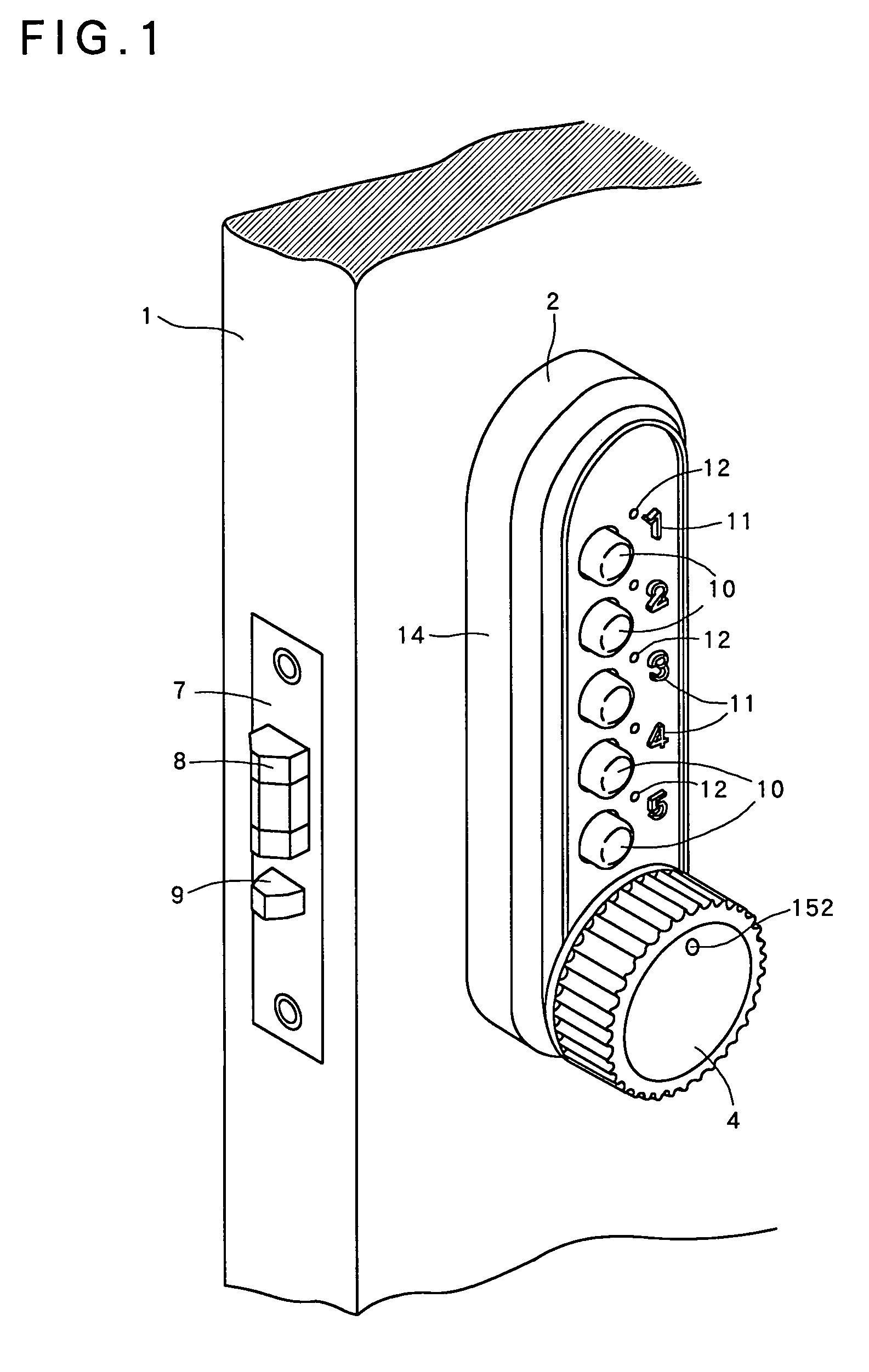
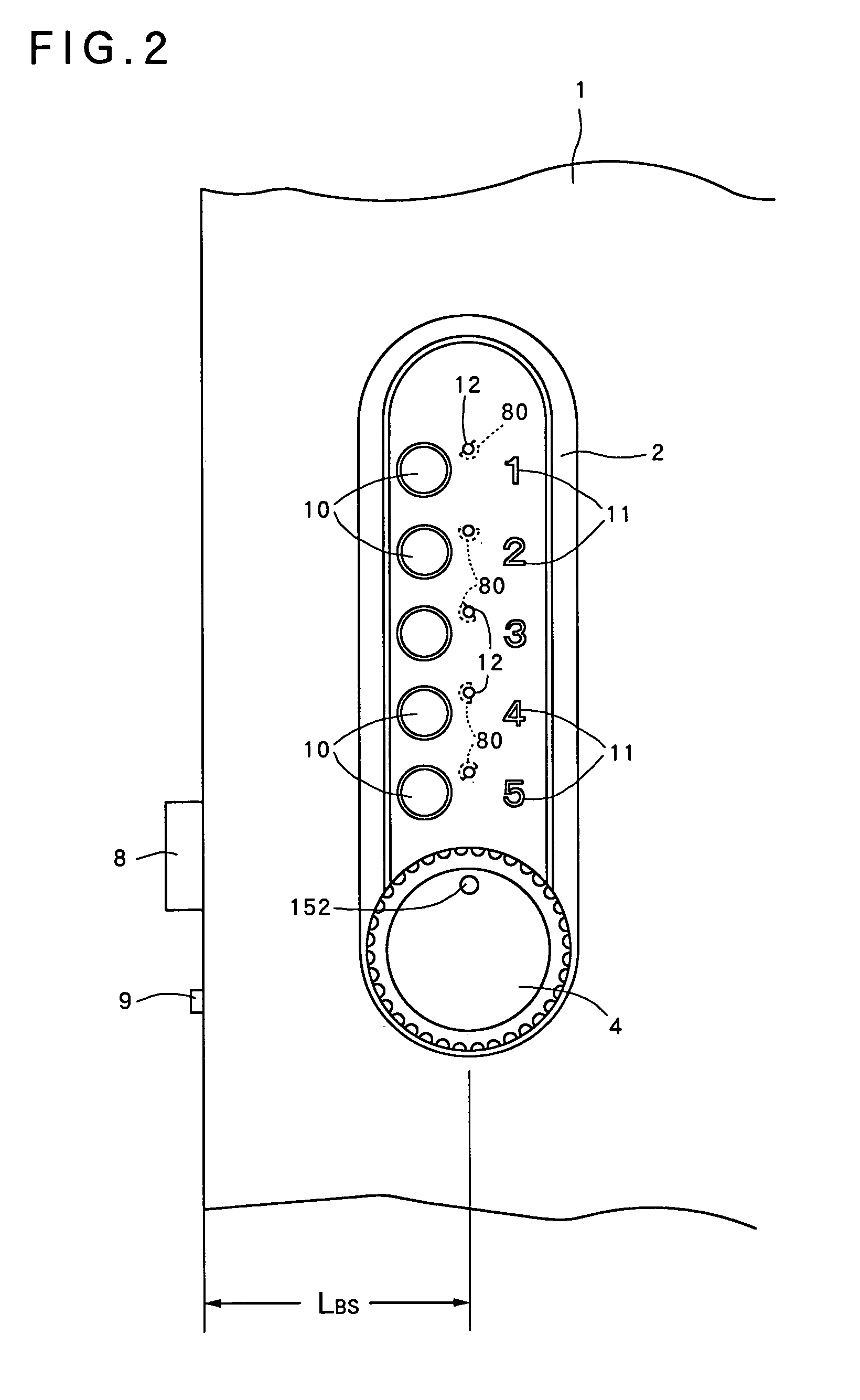
[0106]The present invention will be described hereinafter in the form of one preferred embodiment with reference to the accompanying drawings. In FIGS. 1 through 36, reference numeral 1 denotes a left suspension type door, which one end part on the suspending base side is turnably attached to a framework (both of them are not shown) through a hinge, and a main lock (not shown) of the present invention is embedded in the other side end part.

[0107]A vertically elongated oval-shaped button-operated lock 2 is disposed at the other side end part of the outdoor of the door 1. A seat plate 3 having a generally same configuration as the button-operated lock 2 and having a small thickness is disposed at the indoor side of the door 1.

[0108]The button-operated lock 2 and the seat plate 3 are provided at lower end parts thereof with door handles 4, 5, respectively, such that the door handles 4, 5 can turn independently. A changeover knob 6 such as a thumb turn knob is attached to an upper end p...


PUM


Abstract

There is provided a button-operated lock device capable of increasing a setting amount of information in response to operation of a control button, obtaining a large setting amount and a wide-range of selection thereof, enhancing safety performance, simplifying the structure and achieving a small size and a light-weight, thereby achieving a low manufacturing cost, executing such various operations as setting or inputting information and altering thereof correctly, safely, easily and rationally, and preventing decoding or perceiving of preset or inputted information so that any third party is prevented from making a falsification and / or conversion of this device.The button-operated lock comprises a plurality of control buttons (10) axially displacedly arranged and capable of setting or inputting a predetermined information; a control plate (128) for allowing an unlocking procedure at the time of setting or imputing the predetermined information; a driving cam (16) linked to the control plate (128) and capable of being operatively connected to a pair of door handles (4, 5); and a lock element linked to the driving cam (16), wherein a plurality of same or different information can be set or inputted to each of the control buttons (10) and the plurality of same or different information can be set or inputted every time the control button (10) is operated.

Description

TECHNICAL FIELD[0001]This invention relates to a button-operated lock device capable of increasing a setting amount of information in response to operation of a control button, obtaining a large setting amount and a wide-range of selection thereof, enhancing safety performance, simplifying the structure and achieving a small size and a light-weight, thereby achieving a low manufacturing cost, executing such various operations as setting or inputting information and altering thereof correctly, safely, easily and rationally, and preventing decoding or perceiving of preset or inputted information so that any third party is prevented from making a falsification and / or conversion of this device.BACKGROUND ART[0002]Recently, a keyless lock of the type requiring the use of no key has been popularized as a door lock to be used for individual dwelling houses, companies, shops, hospitals and the like.[0003]As a keyless lock of the type mentioned above, there are a so-called mechanical lock in...

Claims


Application Information

Patent Timeline
Patent Type & Authority Patents(United States)
IPC IPC(8): B65D55/14E05B37/16
CPCE05B37/16E05B37/166Y10T70/726Y10T70/722Y10T70/5788Y10T70/7305Y10T70/5814
Inventor NAKAZIMA, SUSUMUTAKAHASHI, KOICHINAITOU, KENJI
Owner NAGASAWA SEISAKUSHO
Why Eureka
Try Eureka