
Engine

a technology for engines and belts, applied in the field of engines, can solve the problems of insufficient durability, high and v-belts in particular are likely to deteriorate, so as to prevent the temperature in the transmission case from rising, prolong the durability of the v-belt, and prevent premature deterioration of the v-belt

Active Publication Date: 2008-01-08
YAMAHA MOTOR CO LTD
View PDF29 Cites 25 Cited by
  • Summary
  • Abstract
  • Description
  • Claims
  • Application Information

AI Technical Summary

Benefits of technology

[0008]An advantage of the present invention made in view of the situations with the prior art described above is to provide an engine that can prevent the temperature in the transmission case from rising, prevent the V-belt from prematurely deteriorating due to the temperature rise, and extend the durability of the V-belt.
[0009]An embodiment of the present invention is an engine having an engine case on one side of which a V-belt type of continuously variable transmission is provided. The CVT placed in a transmission case and constituted that a V-belt is routed around a drive pulley and a driven pulley. The drive pulley is attached to one end of a crankshaft. The driven pulley is attached to one end of a transmission shaft parallel to the crankshaft. The crankshaft is supported for free rotation with the engine case. One end of the crankshaft is projected in a cantilever fashion from the engine case into the transmission case. The drive pulley is attached to the projected portions, and the transmission case is made as a component separate from or independent of the engine case and supported with the engine case so that a space is present between the engine case and the transmission case.
[0010]The “engine case” as used herein is a general term including the following cases: the crankcase in which the crankshaft is placed, the clutch case in which the clutch mechanism is housed, and the generator case in which the generator is placed. Each case is formed partially or wholly to be integral with other case or cases, or separately formed.
[0011]The invention described above is an engine having an engine case on one side of which a V-belt type of continuously variable transmission (CVT) is provided. The CVT is placed in a transmission case and constituted that a V-belt is routed around a drive pulley and a driven pulley. The drive pulley is attached to one end of a crankshaft. The driven pulley is attached to one end of a transmission shaft placed parallel to the crankshaft. The transmission shaft is supported for free rotation with the engine case. One end of the transmission shaft is made to project in a cantilever fashion from the engine case into the transmission case. A clutch mechanism is attached to part of the transmission shaft located in the engine case. The driven pulley is attached to the projected portion. The transmission case is made as a component separate from or independent of the engine case and supported with the engine case so that a space is present between the engine case and the transmission case.
[0012]The invention described above is an engine having an engine case on one side of which a V-belt type of continuously variable transmission (CVT) is provided. The CVT is placed in a transmission case and constituted that a V-belt is routed around a drive pulley and a driven pulley. The drive pulley is attached to one end of a crankshaft. The driven pulley is attached to one end of a transmission shaft parallel to the crankshaft. The crankshaft and said the transmission shaft are supported for free rotation with the engine cases. One end of the crankshaft and one end of the transmission shaft are projected in a cantilever fashion from the engine case into the transmission case. The drive pulley is attached to the projected portion of the crankshaft. The driven pulley is attached to the projected portion of the transmission shaft. The transmission case is made as a component separate from or independent of the engine case and supported with the engine case so that a space is present between the engine case and said the transmission case.
[0013]According to the invention described above at least part of the side surface of the transmission case that faces the engine case is a resin member. The V-belt is a resinous belt formed by connecting together a plural number of blocks, with part of each block in contact with the drive pulley and the driven pulley being made of a resin member. A lubricant oil chamber formed at the engine case is made to swell out below the transmission case so that a space is present between the lubricant oil chamber and the transmission case. The drive pulley and driven pulley are made up of fixed pulley halves fixed to the crankshaft and transmission shaft and movable pulley halves that can axially slide on the crankshaft and transmission shaft. The movable pulley halves of the drive pulley and driven pulley are placed respectively on the inner side and outer side with respect to the crankshaft direction. A centrifugal clutch mechanism is attached to the transmission shaft on the inner side with respect to the crankshaft direction and adjacent to the driven pulley.

Problems solved by technology

When the V-belt type of CVT is located on the side of the engine case, the temperature in the transmission case is likely to rise due to heat from the engine and heat generated by friction of the V-belt.
The V-belt in particular is likely to deteriorate with the thermal effect and its insufficient durability is a problem.

Method used


Image

  • Engine
  • Engine
  • Engine

Examples


Embodiment Construction

[0039]The embodiments of the present invention will be hereinafter described in reference to the appended drawings.

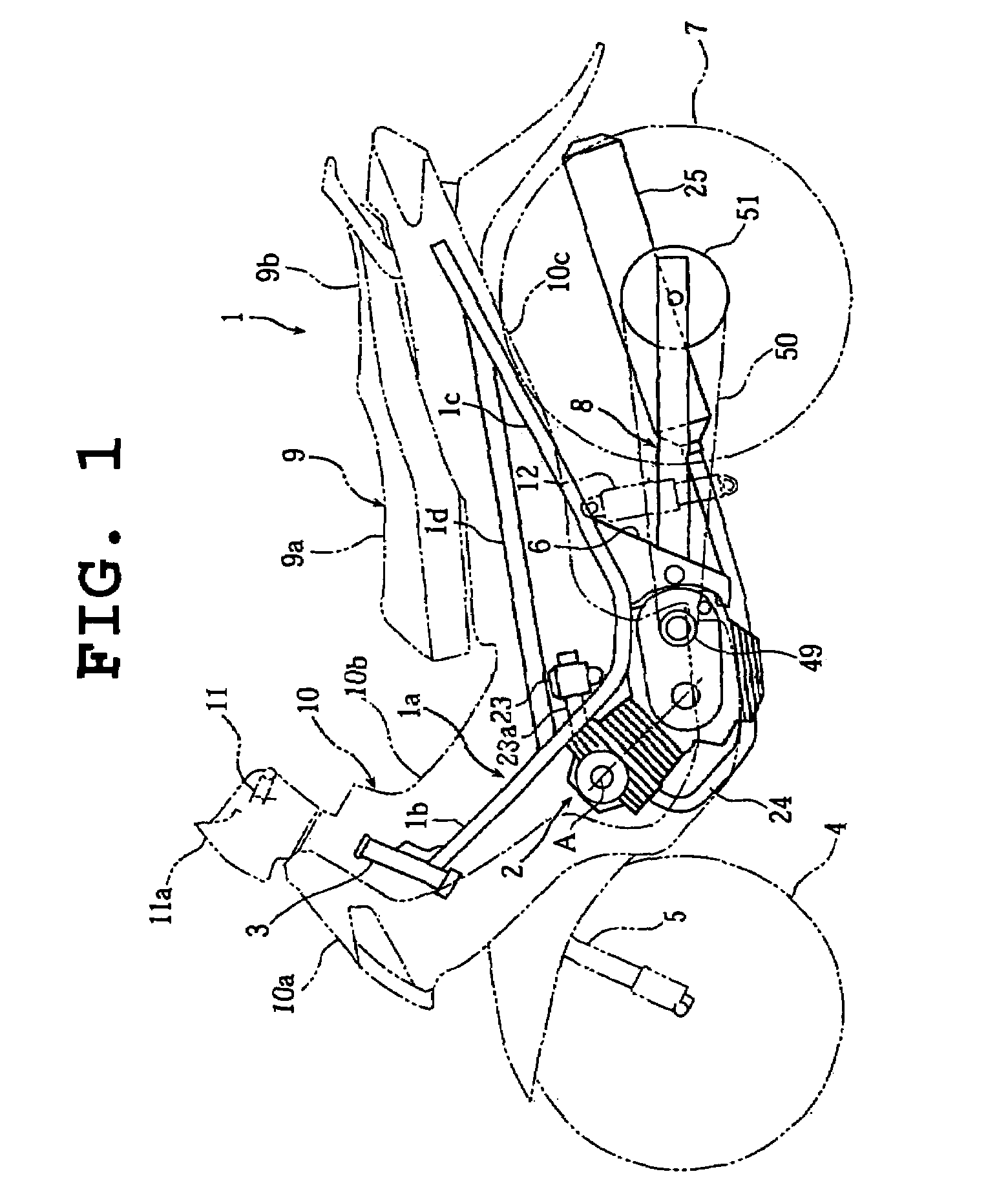
[0040]FIGS. 1 to 15 are explaining a motorcycle engine as an embodiment of the present invention. FIG. 1 is a left side view of a motorcycle on which an engine as an embodiment of the present invention is mounted. FIG. 2 is a sectional plan view along the line II-II in FIG. 6 showing the extended state of the above engine. FIG. 3 is a sectional plan view of the CVT mechanism and the centrifugal clutch mechanism portion of the above engine. FIGS. 4 and 5 are right and left side views of the engine. FIG. 6 is a right side view of the above engine with the CVT mechanism and the centrifugal clutch mechanism removed. FIG. 7 is a right side view of the crankcase of the above engine. FIG. 8 is a sectional rear view along the line VIII-VIII in FIG. 5 of the above crankcase. FIG. 9 is a sectional view of the kick mechanism of the above engine as seen along the line IX-IX in FIG....


PUM


Abstract

An engine having an engine case on one side of which a V-belt type of continuously variable transmission is provided, the CVT being placed in a transmission case and constituted that a V-belt is routed around a drive pulley and a driven pulley, the drive pulley being attached to one end of a crankshaft, the driven pulley being attached to one end of a transmission shaft parallel to the crankshaft, characterized in thatthe crankshaft is supported for free rotation with the engine case, one end of the crankshaft is projected in cantilever fashion from the engine case into the transmission case, the drive pulley is attached to the projected portion, and the transmission case is made as a component separate from or independent of the engine case and supported with the engine case so that a space is present between the engine case and the transmission case.

Description

FIELD OF THE INVENTION[0001]The present invention relates to an engine with a V-belt type of continuously variable transmission (CVT) on one side in the crankshaft direction of the engine case that is appropriate for use, for example, on motorcycles.TECHNICAL BACKGROUND[0002]Some of the engines for use on motorcycles, for example, are provided with a V-belt type of CVT located on the axially outer side of the engine case and comprising a drive pulley attached to one end of the crankshaft, a driven pulley attached to one end of a transmission shaft placed parallel to the crankshaft, and a V-belt placed around the both pulleys.[0003]A conventional engine with such a type of CVT is disclosed for example in a laid-open Japanese patent No. 3095024 constituted that part of the engine case is defined as a transmission case into which one end of the crankshaft and one end of the transmission shaft are made to extend in cantilever fashion, and that their distal ends are provided with the dri...

Claims


Application Information

Patent Timeline
Patent Type & Authority Patents(United States)
IPC IPC(8): B62J13/04F16H7/02B62M7/02F02B61/02F02B75/02F02B75/16F02F1/24F16H57/02F16H61/662
CPCB62M7/02F02B61/02F02B75/16F16G5/166F02B2075/027F02B2275/20Y10T74/2186F16H57/02F16H61/662F16H2057/0203F16H2057/02065F02F2001/245
Inventor OISHI, AKIFUMIISHIDA, YOUSUKE
Owner YAMAHA MOTOR CO LTD
Learn More