Kinematic sensors employing atom interferometer phases

a technology of atom interferometer and phase, applied in the field of kinematic navigation, can solve the problems that prior art atom interferometric sensors designed to serve as accelerometers or gyroscopes are not sufficiently fast for precise kinematic navigation applications

Inactive Publication Date: 2008-01-08
THE BOARD OF TRUSTEES OF THE LELAND STANFORD JUNIOR UNIV
View PDF6 Cites 14 Cited by
  • Summary
  • Abstract
  • Description
  • Claims
  • Application Information

AI Technical Summary

Problems solved by technology

Unfortunately, the best measurement accuracy in atom interferometers is obtained when measurements are performed over time intervals ranging from 10 ms to 500 ms since the accuracy of an atom interferometric measurement increases with measurement time.
Hence, prior art atom interferometric sensors designed to serve as accelerometers or gyroscopes are not sufficiently quick for applications in precise kinematic navigation.

Method used


Image

  • Kinematic sensors employing atom interferometer phases
  • Kinematic sensors employing atom interferometer phases
  • Kinematic sensors employing atom interferometer phases

Examples


performance examples

[0124]The method of invention can be used to restore the rotation matrix for any given body trajectory and rotation under the influence of noise. Since we can restore body orientation independently, as described above, we first examine the performance of rotation matrix R(t) restoration under a relative inaccuracy defined as:

[0125]Δ⁢⁢R⁡(t)≡Tr⁢{[R⁡(t)-Re⁡(t)]T⁡[R⁡(t)-Re⁡(t)]}3,Eq.⁢37

where R(t) is the exact rotation matrix. The recurrent relation causes the roundoff errors for rotation matrix R(t) to increase slowly in time when one performs the calculations with quadrupole precision. Examples of the dependencies ΔR(t) are shown in FIG. 8. They were obtained for a time delay T=5 ms between optical pulses, minimal number of interpolation points ni=3, and body acceleration on the order of g (scale parameter sc=1). Using exact body trajectory and rotation matrices we calculated the phases of the basic and additional atom interferometers. Their difference was used in the analogue of equat...


PUM


Abstract

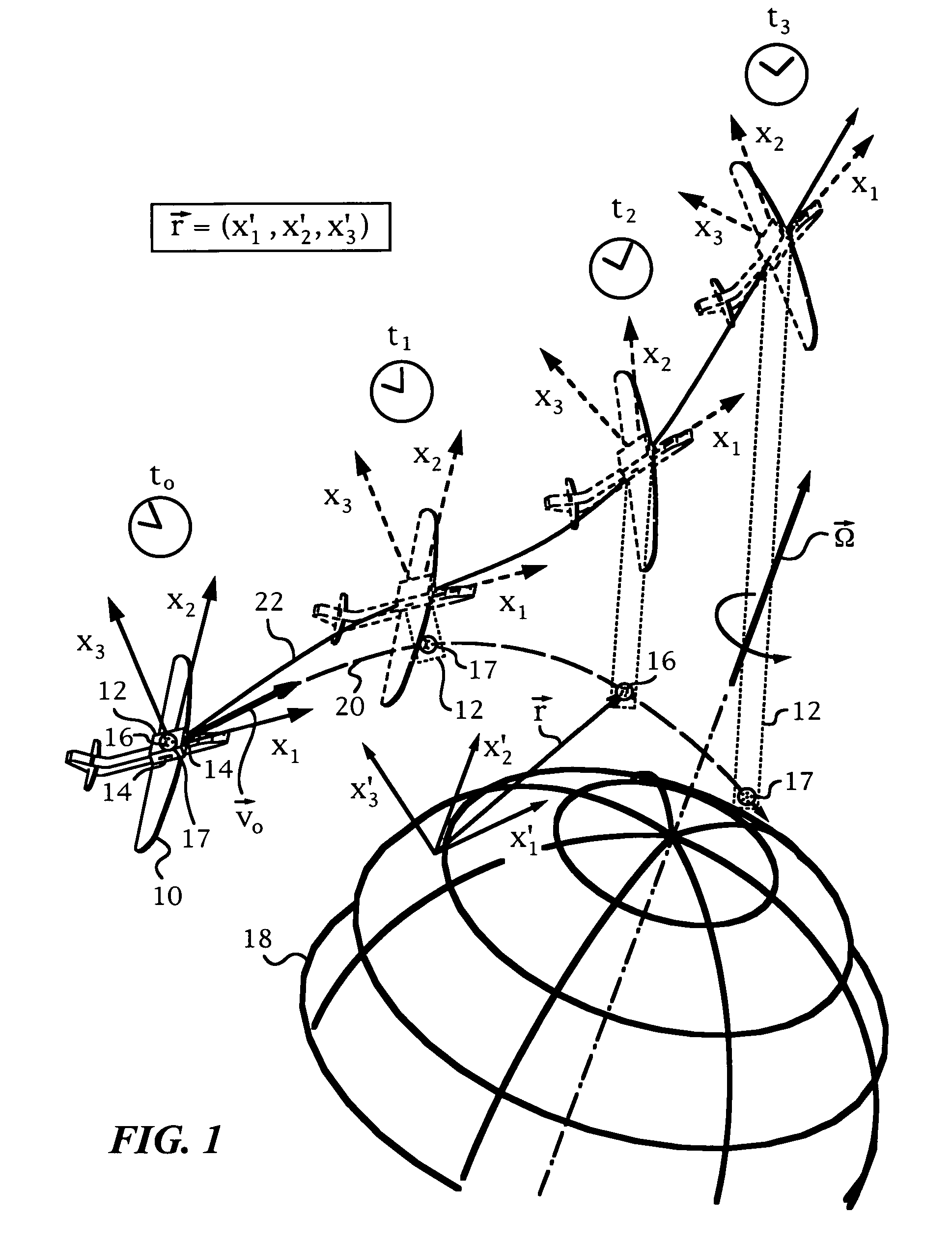
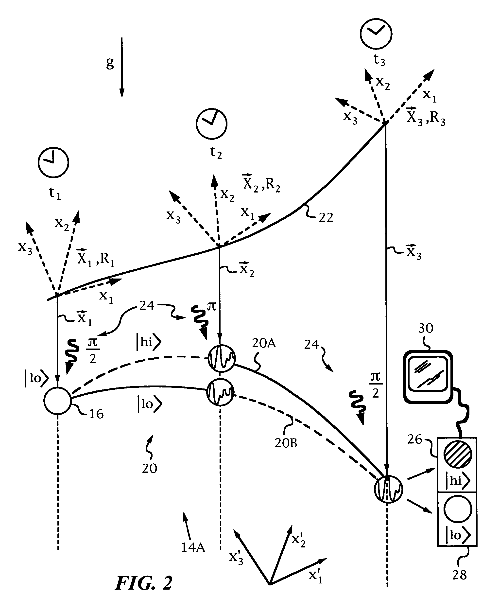
An apparatus and method for determining the coordinates of a body, where the coordinates express the body's inertial or kinematic properties, including, for example, its trajectory. The apparatus and method employ atom interferometers provided in a body frame X of the body whose inertial or kinematic properties are to be studied. During operation, interfering entities used by the atom interferometers are released into a known frame X′, such as an inertial frame or the Earth frame Xe, that is decoupled from the body frame X and an optical pulse sequence is applied to the interfering entities to affect the quantum-mechanical matter-wave phases of the interfering entities as a function of the coordinates. Under these conditions, the coordinates of the body are determined from the phases of the atom interferometers and analytic expressions for the trajectories of the interfering entities under the simultaneous action of the gravity gradient, Coriolis and centrifugal forces.

Description

CROSS-REFERENCE TO RELATED APPLICATIONS[0001]This application claims priority from provisional U.S. patent application No. 60 / 649,302 filed on Feb. 1, 2005 and herein incorporated in its entirety.GOVERNMENT SPONSORSHIP[0002]This application was supported under grant number W911NF-04-1-0047 awarded by DARPA, thereby affording the government certain rights in this invention.FIELD OF THE INVENTION[0003]The present invention relates generally to kinematic navigation employing the quantum effect of atom interference and more particularly the invention allows to navigate by directly using the atom interferometer's phases and without using any accelerometers or gyroscopes.BACKGROUND OF THE INVENTION[0004]For the purposes of the present invention atom interferometry refers generally to quantum mechanical interference processes that involve entities having a rest mass. Among other, such entities include atoms, ions and molecules. For a general overview of the quantum mechanical process of ma...

Claims


Application Information

Patent Timeline
Patent Type & Authority Patents(United States)
IPC IPC(8): H05H3/00G01C21/16
CPCG01C19/58G01C21/16H05H3/04
Inventor KASEVICH, MARK A.DUBETSKY, BORIS
Owner THE BOARD OF TRUSTEES OF THE LELAND STANFORD JUNIOR UNIV
Why Eureka
Try Eureka