RFID transducer alignment system

a technology of rfid transducer and alignment system, which is applied in the direction of burglar alarm mechanical actuation, burglar alarm by hand-portable article removal, instruments, etc., can solve the problems of not being able to apply alternatively new ways, and not being able to provide geometric alignment functionalities in common rfid technology. , to achieve the effect of enhancing the industry

Inactive Publication Date: 2008-01-15
ABR
View PDF24 Cites 104 Cited by
  • Summary
  • Abstract
  • Description
  • Claims
  • Application Information

AI Technical Summary

Benefits of technology

[0013]The present invention is directed to a new application for RFID technology that is intended to enhance the industry as a whole. The RFID system of the present invention utilizes certain design methodologies so as to provide inexpensive and uncomplicated apparatus for detecting and indicating various RFID tag-to-RFID transponder sense coil alignments.
[0014]The present invention provides a simple, functionally enhanced, and new RFID system concept, wherein presently available RFID systems have opportunity to be improved upon or expanded by various new features and / or functionalities, including the capacity to detect manifold parameters of alignment. The present invention further provides a new type of RFID system specifically designed for the dental industry, medical imaging systems, and other such industries, including use with digital radiography. The present invention and new technology also provides a new RFID system having new types of RF transponders, RF readers, RF tag devices, and x-ray film holders. The new technology allows presently utilized dental x-ray films to be placed into a re-devised, intelligent and more comfortable (for the patient) film holder. The present invention and new technology also provides for embedding an RF tag device directly with an x-ray sensitive film, and additionally may be applied to contemporary x-ray systems or digital x-ray systems, allowing contemporary x-ray films or digital x-ray imaging sensors to be critically aligned to a given dental x-ray machine head apparatus, rendering repeat imaging unnecessary.
[0015]The present invention also provides a new RFID system, wherein dental x-rays may be taken with great accuracy resulting from the ability to denote critical alignment of an x-ray emissions apparatus to a dental x-ray film or digital x-ray imaging sensor in a patient's mouth, and in a non-contact manner. The system of the present invention may be configured to denote critical alignment of a dental x-ray film or digital x-ray imaging sensor within a patient's mouth without the need for commonly used special tools, procedures or devices. The new RFID system may be configured to store patient and other information in the RF tag device and / or x-ray film holder.
[0016]The present invention includes a new RFID system for use with x-ray and / or other radiography imaging apparatus so as to provide an automatic RF tag seek mode of operation. For example, a given x-ray head apparatus may be configured to move on its own accord when prompted by the RFLD system. When enabled, the x-ray head apparatus may locate a (perhaps) hidden RF tag device, such as during a dental application, and ultimately align itself to a given located RF tag device. The x-ray head apparatus may be further configured to automatically obtain a.desired x-ray image, and / or retrieve or store certain data from / to an RF tag. The x-ray head apparatus may be further configured so that the apparatus cannot activate and provide a radiograph unless / until a predetermined alignment to a given RF tag device has occurred. Such a system provides a new safety mechanism against impromptu enabling of an x-ray machine apparatus and thus reduces x-ray exposure for the patient.
[0021]The present invention improves upon the current designs of certain RFID transponder devices by providing a system for selection and indication of a given RF transponder's explicit carrier transmit drive signal waveform or waveforms by various devices and circuits, including either or both audio and visual techniques and / or apparatus. The system may also provide for indication of a given RF transponder's carrier transmit amplitude or amplitudes by such devices, circuits and techniques. The system may further provide for indication of the presence of a given RF transponder's carrier transmit signal or signals from such devices, circuits and techniques. The system also may provide for indication of the presence of a given RF transponder's carrier transmit / data receive coil or coils. Further, the system may provide for selection, as well as the indication of selection, of one or more carrier transmit / data receive coils attached to a given RF transponder. Also, the system may provide for the indication of the current mode of operation of a given RF transponder (such as idle or seek mode) by various devices and circuits, including either or both audio or visual techniques and / or apparatus.
[0022]The present invention improves upon the current designs of certain RFID transponder devices by providing a system for on-the-fly and / or in-situ RF tag programming and the indication of the same by various devices and circuits, including either or both audio or visual techniques and / or apparatus. The system may provide for sensing various parameters of alignment, including the parameter of critical alignment, in a fixed or variable three-dimensional space and indication of the same by such devices, circuits and techniques. The system may further provide for audio instruction and / or feedback for a user in the course of operation, whether in the form of tones and / or voice by various devices and circuits. Further, the system may provide for audio instruction and / or feedback for a user in the course of operation, whether in the form of tones and / or voice, wherein pitch and / or volume, or expression, or such, by said various devices and circuits, that might be selected and / or managed by a given RF transponder's response to certain sensed system signals or conditions, alignment parameters, user input, or other predefined variables.

Problems solved by technology

However, current RFID technology has routinely been limited to its namesake: product “identification”.
Thus, the technology has not been applied in alternatively new ways, or with regard to differing applications.
Accordingly, common RFID technology does not provide for geometric alignment functionalities, such as indicating best non-contact alignment between an x-ray emitter and an x-ray film during the positioning of one to the other.
During the traditionally standard process of taking dental x-rays, special tools and several tedious steps are often required.
Aside of the general need for special alignment tools, the disadvantages of the above two options are several: 1) often additional x-rays are required to be taken because of improper alignment of the x-ray head apparatus to the x-ray film, especially when the location / position of the x-ray film is manually estimated, and often, when; 2) the RINN SYSTEM is improperly located / positioned in a given patient's mouth, which creates; 3) loss of both time and supplies, increasing expense, and, which additionally; 4) exacerbates a given patient's discomfort.
Such technology had not been used for exacting a critical alignment of an x-ray head apparatus to an (often hidden) x-ray film.
One issue in creating a dental-oriented non-contact RFID transducer system is that a given dental RF tag ought be physically smaller than an accompanying dental RF carrier transmit / data receive coil.
Another issue to operational practicality for a dental application is that “non-contact” operation be obtained, wherein a given x-ray head apparatus would never (intentionally, nor need to be caused to) touch a patient's face, in the course of alignment of the x-ray head apparatus to the dental RF tag within a patient's mouth.
This issue is not in the least trivial since known RFID technology did not allow for spacious RF tag distance sensing in wholly scaled-down RFID systems.
Various common RF tags currently available were used in test beds, and were found to be grossly lacking as it concerned desired functionality and operational distance to a similarly available RF transponder.
Thus, commonly available systems were both non-ideal and impractical for a dental x-ray application.

Method used


Image

  • RFID transducer alignment system
  • RFID transducer alignment system
  • RFID transducer alignment system

Examples


Embodiment Construction

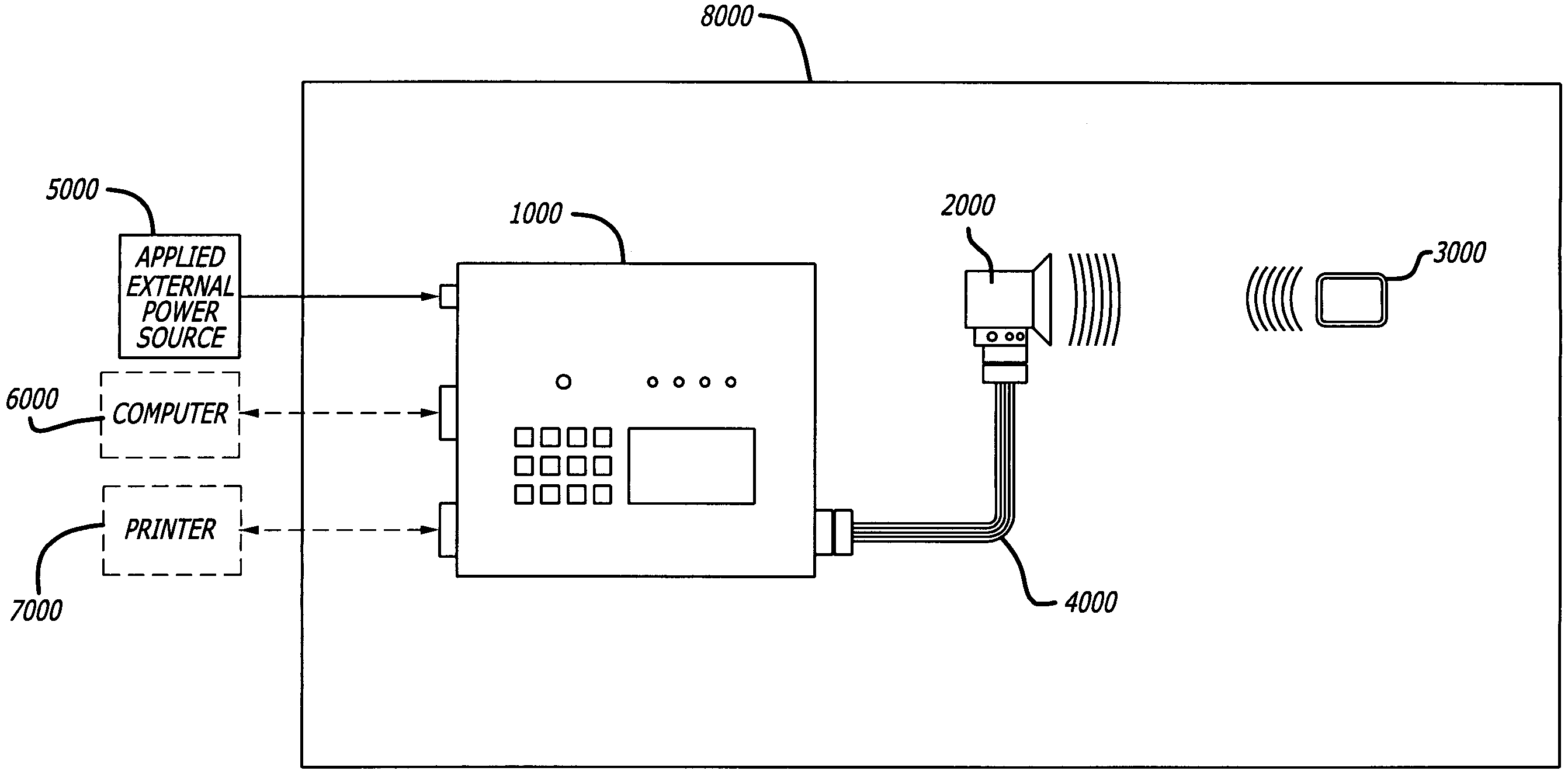
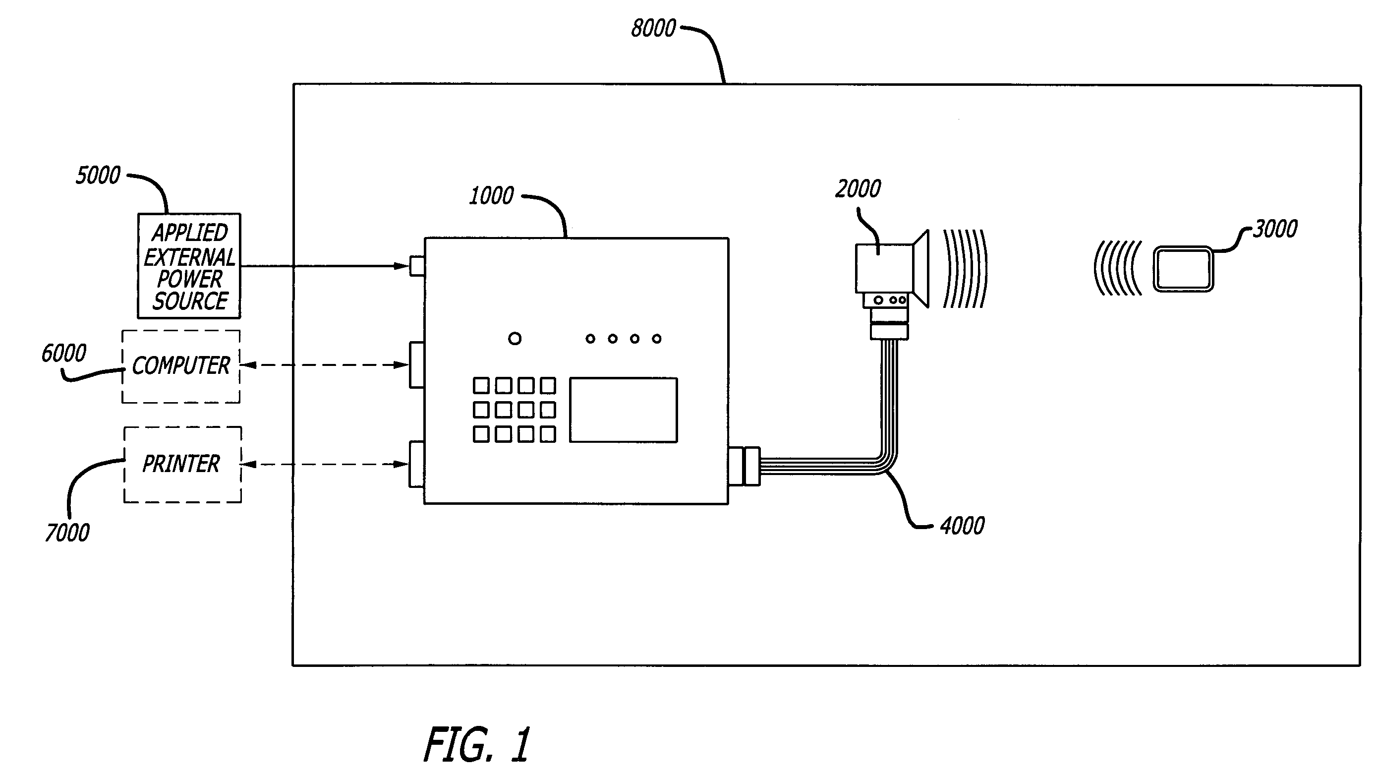
[0044]As shown in the drawings for purposes of illustration, the present invention is directed to a beneficial and novel electronic design, the basis of which is founded on RFID (radio frequency identification) technology. The present invention provides an altogether new RFID application having enhanced levels of utility and practical functionality over present-day commonlstandard uses for / of the RFID technology. This RFID system is beneficially applicable to those apparatus or products that require, or might make use of non-contact power control and / or operation, non-contact accessibility or enabling, and non-contact entry. The invention is also useful for those products, apparatus, or devices that require or might make use of non-contact object / target sensing or detection, intelligent non-contact sensor response systems, and non-contact object / target data programming and / or data retrieval. The invention may also be applied to systems requiring non-contact alignment capability for ...


PUM

PropertyMeasurementUnit
sensing-distanceaaaaaaaaaa
sensing distanceaaaaaaaaaa
frequencyaaaaaaaaaa

Abstract

A radio frequency identification (RFID) system having the capacity to detect various geometric parameters of alignment. The described system is configured for use with dental x-ray, medical imaging and treatment, and customary and digital radiography apparatus, but is not restricted to such apparatus or applications. The system may include a multiplicity of RF transponders, RF tags, and RF readers, wherein each RF tag may include one or more carrier receive / data transmit coils and wherein each RF reader may include one or more carrier transmit / data receive coils, and wherein each coil of an RF tag or RF reader may resonate at one or more, and / or, at the same or differing frequencies. An RF tag located about an x-ray sensitive film or device, and an RF reader located about a dental x-ray machine or apparatus, are configured to be critically aligned, one to the other, rendering repeat imaging unnecessary.

Description

CROSS-REFERFNCES TO RELATED APPLICATIONS[0001]This application claims the benefit of U.S. Provisional Application Ser. No. 60 / 602,223, filed Aug. 16, 2004 and U.S. Provisional Application Ser. No. 60 / 602,751, filed Aug. 18, 2004, the contents of which are hereby incorporated herein by reference.BACKGROUND OF THE INVENTION[0002]This invention relates generally to providing enhanced functionality with regard to common radio frequency identification (RFID) technologies and devices, and more specifically, to the utilization of electromagnetic flux fields of at least one predetermined radio frequency (RF) to detect various geometric alignment conditions of two or more items, devices, or apparatus to each other in three dimensional space, for example, as an x-ray system positioning apparatus, the invention provides for detection and indication of the relative positionings, ergo: various geometric alignment conditions, as might exist between an x-ray emissions device, and, an RFID tag coup...

Claims


Application Information

Patent Timeline
Patent Type & Authority Patents(United States)
IPC IPC(8): G08B13/14A61B6/14G03B42/02G03C5/16
CPCA61B6/14A61B6/587G03B42/047
Inventor HOMANFAR, RAMININCZE, BELAMASSEY, DAVID
Owner ABR
Why Eureka
Try Eureka