Surface texture measuring instrument

a technology of surface texture and measuring instruments, which is applied in the direction of instruments, material analysis using wave/particle radiation, nuclear engineering, etc., can solve the problems of inability to obtain the relationship in advance in view of material dependence, inability to accurately measure the effect of surface texture, and inability to accurately measure the surface texture, etc., to achieve the effect of reducing vibration, reducing vibration, and reducing vibration

Active Publication Date: 2008-01-15
MITUTOYO CORP
View PDF14 Cites 11 Cited by
  • Summary
  • Abstract
  • Description
  • Claims
  • Application Information

AI Technical Summary

Benefits of technology

[0011]An object of the present invention is to provide a surface texture measuring instrument that can perform high-accuracy calibration.

Problems solved by technology

However, the above-described relationship is strongly material-dependent regarding the workpiece.
Owing to this, it is extremely difficult to obtain the relationship in advance in view of the material-dependency.
However, since mechanical and optical elements of the measuring instrument must be disposed in positions different from the position of the near-field scanning optical microscope, there are generated uncertainty of calibration in terms of time and space.
Especially, the uncertainty in terms of space may be a serious bottleneck for the near-field scanning optical microscope that performs nanometer-length measurement on the workpiece.
Or, if the measuring instrument is moved to the length measurement position of the near-field scanning optical microscope in order to solve this bottleneck, the movement axis generated in the movement will cause further uncertainty, thus resulting in submicrometer-level uncertainty.

Method used


Image

  • Surface texture measuring instrument
  • Surface texture measuring instrument
  • Surface texture measuring instrument

Examples


first embodiment

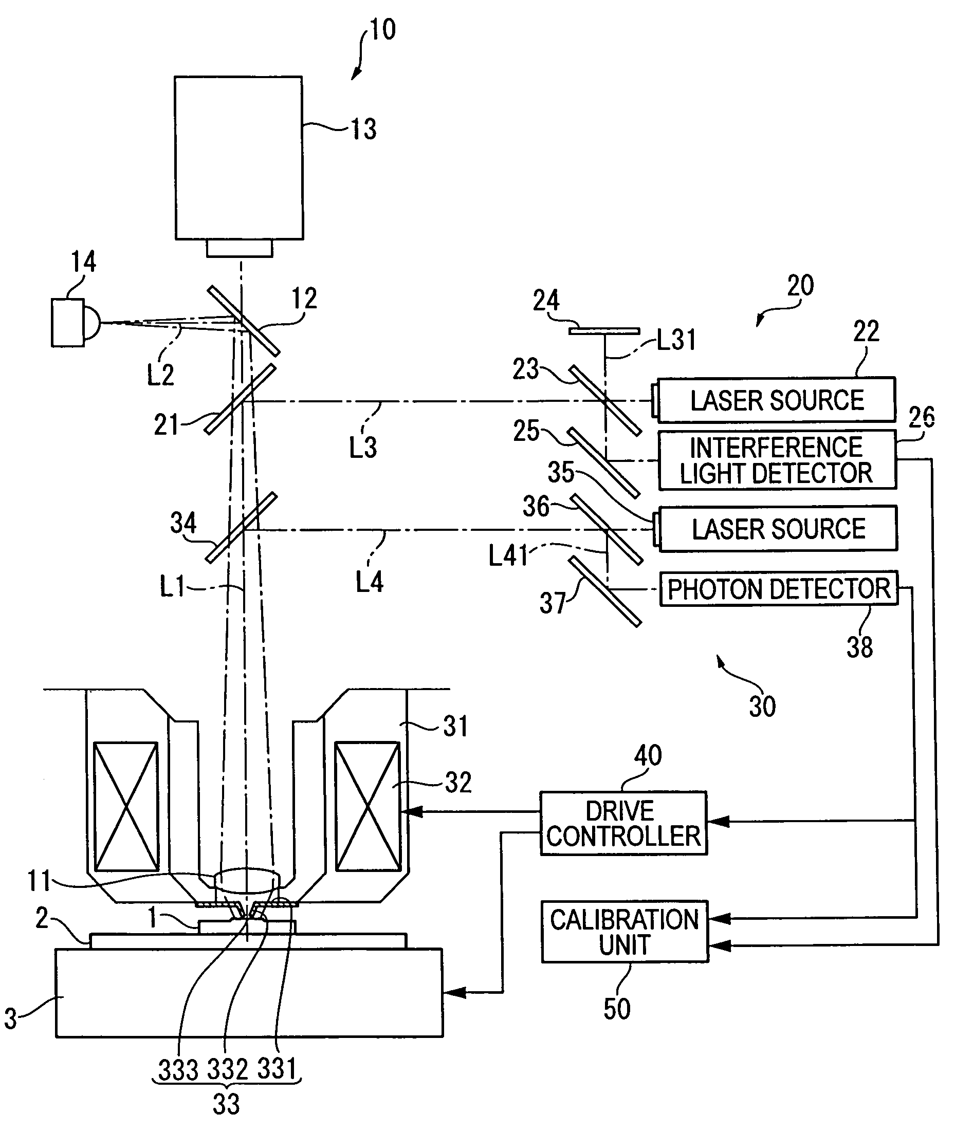
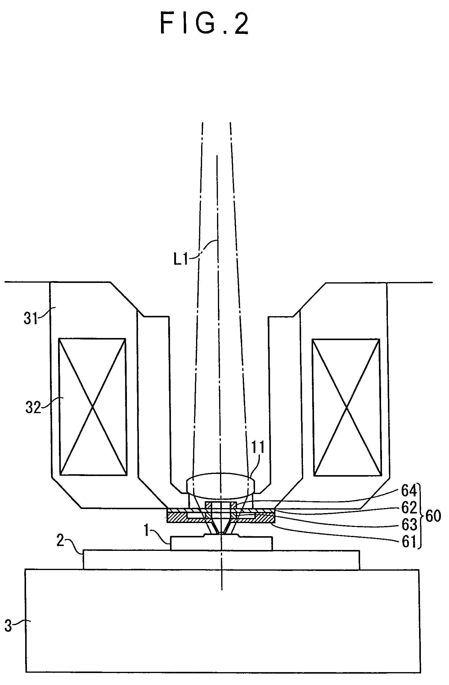
[0037]FIG. 1 shows an optical microscope of a first embodiment. The optical microscope includes a table 2 on which a workpiece 1 is mounted, a relative movement unit 3 that moves the table 2 three-dimensionally (in horizontal, longitudinal, and vertical directions), an optical observation unit 10 that images and observes the workpiece 1 with a camera etc., a laser length-measuring unit 20, a near-field measuring unit 30, a drive controller 40, and a calibration unit 50.

[0038]The optical observation unit 10 includes an objective lens 11, a half-mirror 12 arranged on an optical path L1 of the objective lens 11, a CCD camera 13 (image pickup unit) arranged on the optical path L1 of the objective lens 11 to image a light transmitted through the half-mirror 12 (a reflected light from the workpiece 1), and a light source 14 arranged on an optical axis L2 orthogonal to the optical axis L1 of the objective lens 11 to irradiate light toward the half-mirror 12.

[0039]The laser length-measuring...

second embodiment

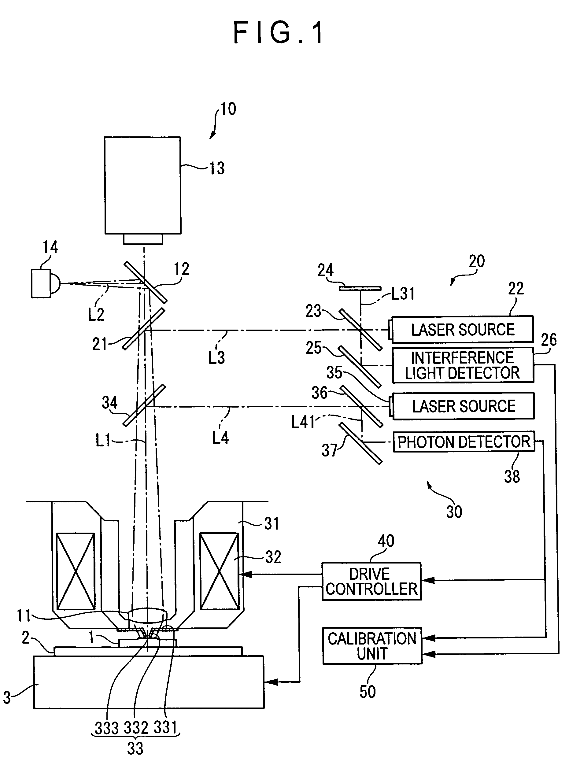
[0060]FIG. 2 is a schematic illustration showing the primary portion of the optical microscope according to a second embodiment, and FIG. 3 is an enlarged perspective view showing a near-field probe applied to the second embodiment. Note that, when describing the drawings, the same components as the first embodiment will be assigned with the same reference numbers and the description thereof will be omitted.

[0061]The optical microscope of the second embodiment has a near-field probe different from that of the optical microscope in the first embodiment.

[0062]A near-field probe 60 of the second embodiment includes a first supporting body 61, a second supporting body 62 coupled to the first supporting body 61, a piezoelectric element 63 disposed between the first and second supporting bodies 61, 62, a balancer 64 disposed on a surface of the second supporting body 62 opposite to the piezoelectric element 63.

[0063]As shown in FIG. 3, the first supporting body 61 includes a ring-like fir...


PUM


Abstract

A surface texture measuring instrument provided with a near-field measuring unit (30) including a near-field probe (33) that forms a near-field light at a tip end thereof when a laser beam is irradiated, a laser source (35) that generates the laser beam to be irradiated on the near-field probe (33), a detection element (38) that detects scattering effect of the near-field light generated when the near-field probe (33) is moved close to a workpiece (1), and an actuator (32) that displaces the near-field probe (33) and the workpiece (1) in a direction moving close to / away from each other, includes: a laser length-measuring unit (20) that measures a relative distance between a reference position and the workpiece (1) in the vicinity of the tip end of the near-field probe (33) or a relative distance between the reference position and the near-field probe (33).

Description

BACKGROUND OF THE INVENTION[0001]1. Field of the Invention[0002]The present invention relates generally to surface texture measuring instruments, and more particularly to surface texture measuring instruments for measuring surface texture of a workpiece utilizing evanescent light (near-field light).[0003]2. Description of Related Art[0004]An optical microscope has been known as an example of a surface texture measuring instruments for measuring surface texture of a workpiece utilizing evanescent light (near-field light), which is disclosed in Document 1 (JP-A-9-243649).[0005]The optical microscope includes an optical waveguide probe having, at a tip end thereof, an extremely small opening with the diameter smaller than the wavelength of the light, an evanescent light generator that generates evanescent light on a surface of a sample, and an evanescent light detector that condenses and detects scattered light of the evanescent light, which is scattered at the tip end of the optical w...

Claims


Application Information

Patent Timeline
Patent Type & Authority Patents(United States)
IPC IPC(8): G02B7/04H01J3/14G01B11/30G01Q20/02G01Q30/02G01Q60/18G01Q60/20
CPCG01Q30/02G01Q60/22G01Q40/00
Inventor HIDAKA, KAZUHIKO
Owner MITUTOYO CORP
Why Eureka
Try Eureka