Vibrator for bone conducted hearing aids

a technology of vibrating device and hearing aid, which is applied in the direction of transducer casing/cabinet/support, electrical transducer, frequency/directions obtaining arrangement, etc., can solve the problems of user discomfort, eczema, and surgical operation in the middle ear, which is a relatively complicated procedure, and requires an extensive surgical installation procedure on the middle ear bones. , to achieve the effect of reducing magnetic leakag

Inactive Publication Date: 2008-01-15
OSSEOFON
View PDF24 Cites 18 Cited by
  • Summary
  • Abstract
  • Description
  • Claims
  • Application Information

AI Technical Summary

Benefits of technology

[0015]According to a preferred embodiment the magnetic circuit is formed as a casing aro

Problems solved by technology

This causes the user a feeling of pressure, discomfort, and sometimes even eczema.
Such a connection, however, requires a surgical operation in the middle ear which is a relatively complicated procedure.
Although such a solution leaves the auditory meatus free, it nevertheless requires an extensive surgical installation procedure on the middle ear bones.
Even if the bone conduction hearing aid devices have made it possible for more people to benefit from a

Method used


Image

  • Vibrator for bone conducted hearing aids
  • Vibrator for bone conducted hearing aids
  • Vibrator for bone conducted hearing aids

Examples


first embodiment

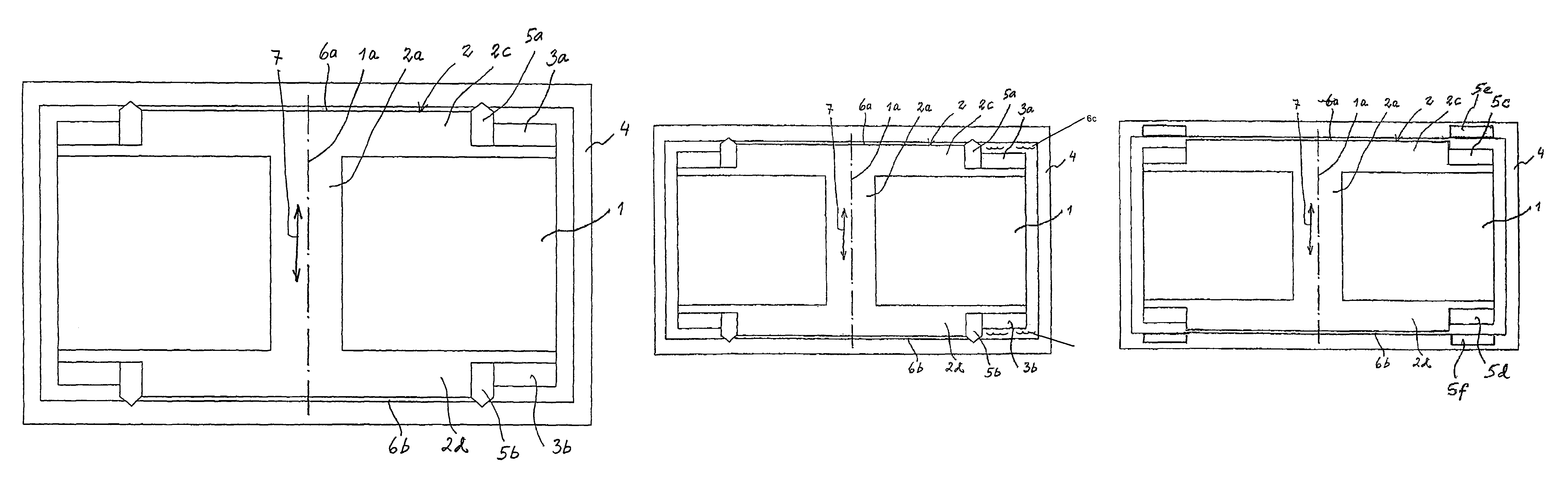
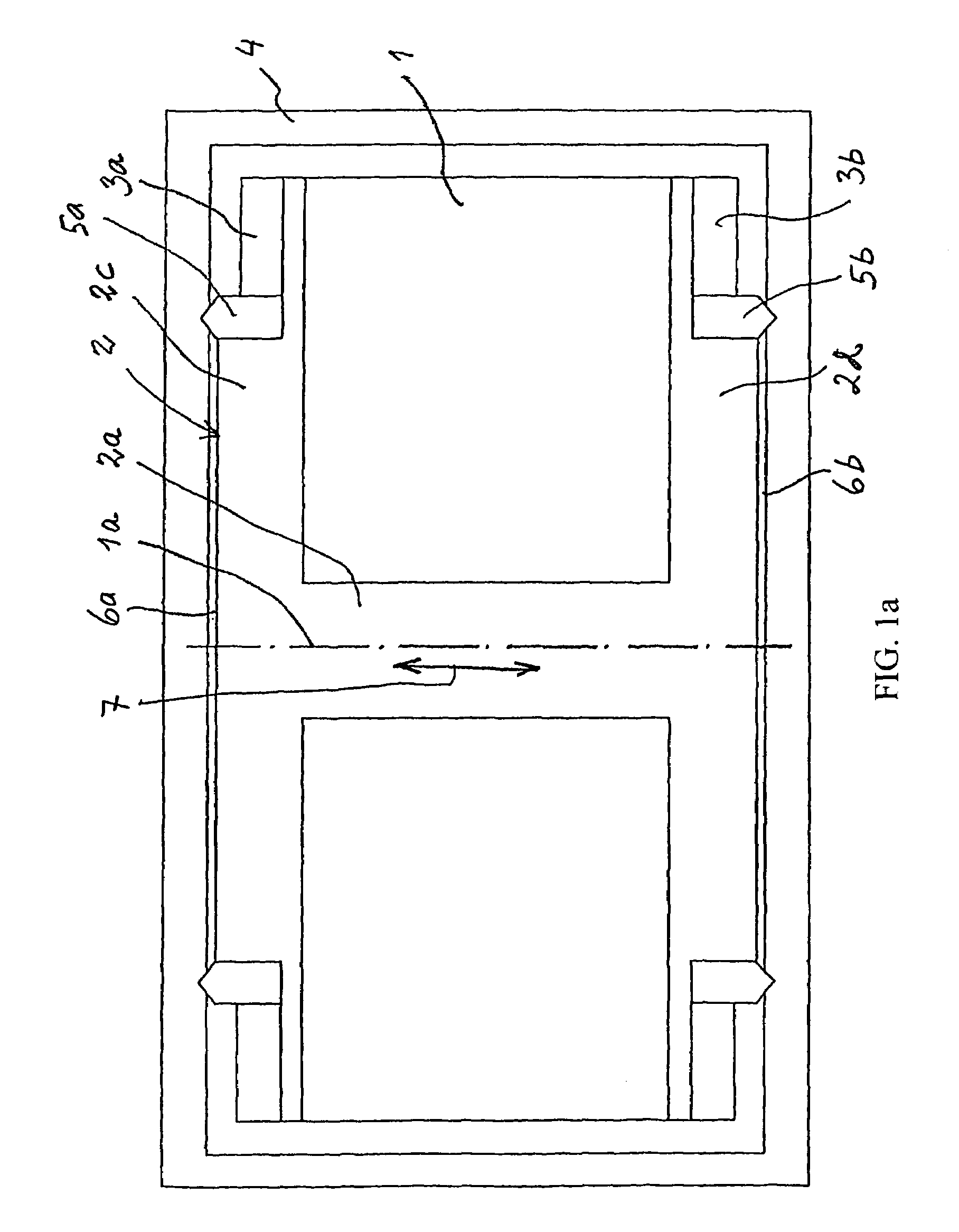
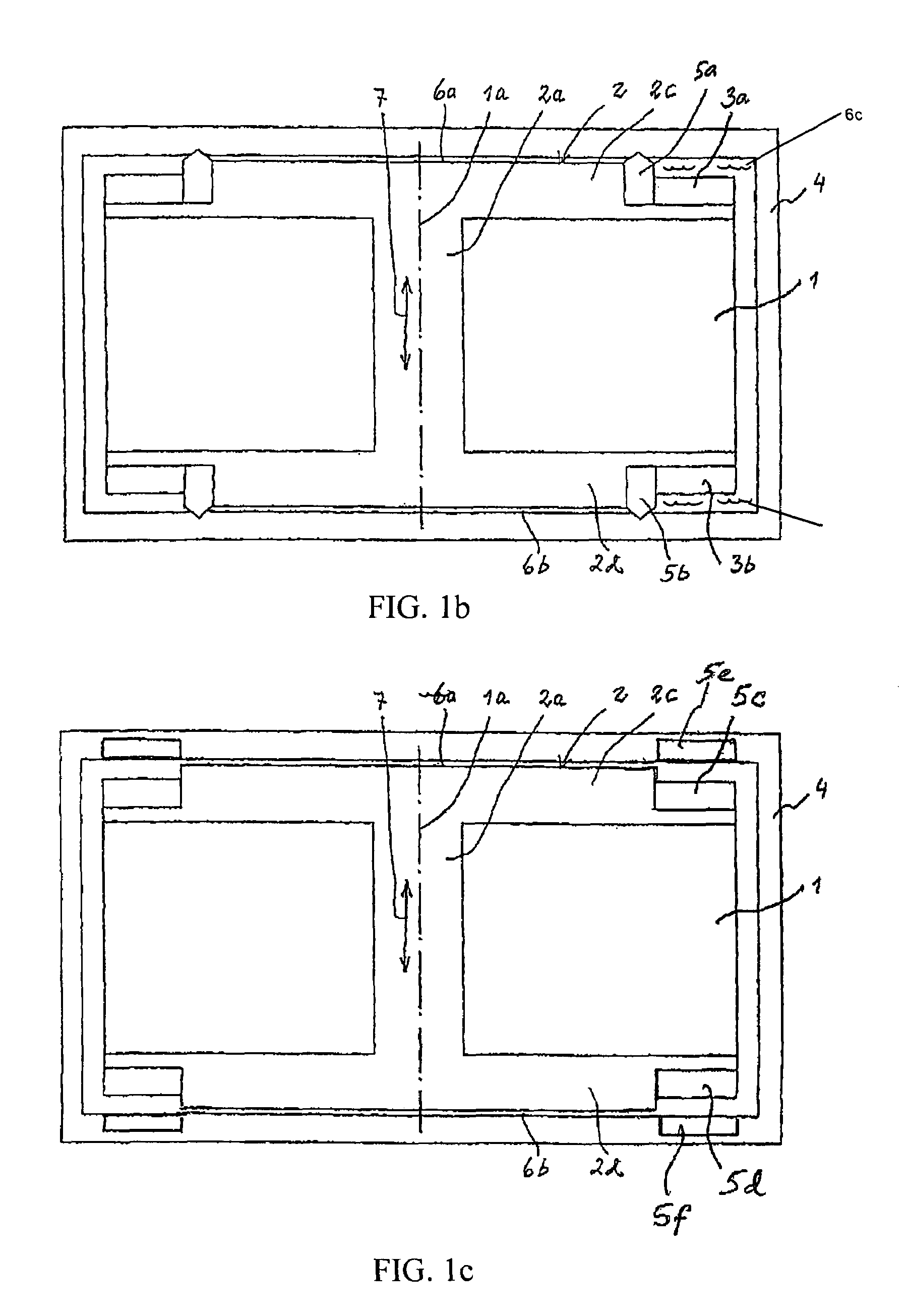
[0028]As all of the embodiments of the vibrator are rotation symmetrical only one half of each vibrator device is shown in the figures, except from FIG. 1. FIG. 1 shows a cross-section through the centre axis 1a of the vibrator. The vibrator comprises a coil 1 which is wound around a bobbin base 2 with a core 2a and two side walls 2c, 2d. In the two side walls there are two outer, peripherally located, annular recesses in which two axially magnetized annular permanent magnets 3a, 3b are attached. The entire coil and magnet arrangement is housed in a casing 4 which forms a part of the magnetic circuit and protects the vibrator and reduces magnetic leakage. The bobbin base and the casing are made of a material with high magnetic conductivity. Inner spring mechanisms 5a, 5b are arranged between the side walls of the bobbin base and the casing so that the coil and magnet arrangement is centered in the casing in its rest position with two air gaps 6a, 6b of the same size between the side...

third embodiment

[0036]The static and dynamic magnetic fields generated by this third embodiment are illustrated in FIGS. 8 and 9. Again, it should be clear that the magnetic fields are substantially separated, but they coincide where this is best needed, i. e. in the air gaps. Specifically, the static field only goes through a part of the construction and the dynamic field does not go through the permanent magnets.

[0037]In the embodiments which have been illustrated so far the permanent magnets are axially magnetized. In FIG. 10 there is an example where the permanent magnets 3a, 3b are radially magnetized. The magnets are annular and arranged on the end surfaces 8a, 8b of the side walls of the bobbin. Even in this case the static and dynamic fields are separated, as illustrated in FIGS. 11 and 12. Specifically, the static field does not in any case go through the core 2a of the coil. The casing 4 protects the entire construction.

[0038]As mentioned by way of introduction the vibrator is specificall...


PUM


Abstract

A vibrator for a bone conduction type hearing aid device. The vibrator includes a coil for generating a dynamic magnetic field and two permanent magnets for generating a static magnetic field. The two permanent magnets are working independently from each other in the magnetic circuit and an arranged in such a way that the static and dynamic magnetic fields are substantially separated from each other, but coinciding in the air gaps formed between the coil and magnet arrangement and the casing, whereby the vibrator provides an axial force.

Description

CROSS-REFERENCES TO RALATED APPLICATIONS[0001]This application claims priority to Swedish patent application 0002073-5 filed 2 Jun. 2000 and is the national phase under 35 U.S.C. § 371 of PCT / SE01 / 01227 filed 21 May 2001.FIELD OF THE INVENTION[0002]The present invention relates to a vibrator for hearing aid devices of the bone conduction type, ie hearing aid devices by which the sound information is mechanically transmitted via the skull bone directly to the inner ear of a person with impaired hearing. The vibrator can be used for traditional, bone anchored as well as implanted bone conduction hearing aid devices.BACKGROUND OF THE INVENTION[0003]For persons with impaired hearing, the hearing aid devices which are mainly used today are those based on the principle that the sound is amplified and fed into the auditory meatus and stimulates the eardrum from the outside. In order to prevent feedback problems in these devices, the auditory meatus is almost completely plugged by a hearing...

Claims


Application Information

Patent Timeline
IPC IPC(8): H04R25/00H04R1/28
CPCH04R25/606H04R11/02H04R9/066H04R9/025H04R2460/13
Inventor ANG.SNES, KRISTIAN
Owner OSSEOFON
Why Eureka
Try Eureka