In ground lighting fixture with adjustable lamp

a technology of ground lighting and adjustable lamps, applied in the field of ground lighting fixtures, can solve the problems of reducing the efficiency and ease of control of the direction of illumination, affecting the effect of lighting effect, and affecting the appearance of the surrounding vegetation, so as to reduce the risk of fire, prevent the accumulation of debris, and ensure the effect of safety

Active Publication Date: 2008-01-22
HUNTER INDUSTRIES
View PDF14 Cites 36 Cited by
  • Summary
  • Abstract
  • Description
  • Claims
  • Application Information

AI Technical Summary

Benefits of technology

[0009]It is an advantage of the present invention to provide a single in-ground lighting fixture that can be placed in the ground to emit a beam that is either directed upward, perpendicular to the ground surface, or angled.
[0010]It is a further advantage of the present invention to provide an in-ground lighting fixture that allows multi-axis adjustment of the beam.
[0011]Still another advantage of the present invention is to provide one or more protective lenses that prevent build up of debris on the lamp face to reduce fire hazards commonly associated with well lights.
[0012]In an exemplary embodiment, the in-ground, or “well light”, fixture comprises a hollow cylindrical housing with a first, flat end and a second, angled end. Either the flat end or the angled end can be used as the upper end depending on the preference of the user and the purpose for which the lighting fixture will be used.
[0013]In the preferred embodiment, the lamp assembly includes a pair of pivots that extend from diametrically opposite sides of the assembly, where each pivot has a circumferential edge that is configured to slide within a channel running along the length of the housing. The combination of the pivot edges and their corresponding channels allows the lamp assembly to be positioned near either end of the housing depending on whether the fixture is to be installed with the angled or flat end up. The same combination of the pivots and the channels forms a gimble for varying the angle of the lamp assembly within the housing. The use of the flat end or angled end of the housing and the adjustability of vertical position and the angle of the lamp assembly provide the maximum flexibility with a single fixture.
[0014]The lamp assembly comprises an enclosure with a base and an upper ring that retains the lamp within the assembly. The upper ring has threads on its inner sidewall that mate with threads on the outer surface of the upper edge of the base to enclose the edges of the lamp. The lamp is preferably a sealed beam PAR lamp, but may be a combination of a halogen lamp, a parabolic reflector and a window or lens disposed over the lamp and held in place by the upper ring to enclose and protect the lamp against contaminants. The lamp assembly is preferably watertight. A socket is located within the base for providing electrical connection between the lamp and wires that are fed through the wall of the base.

Problems solved by technology

Landscape lighting fixtures, most of which are mounted at or above ground level can be considered to appear somewhat incongruous with the surrounding vegetation during daylight hours, when the illumination function is not in use.
Further, because of the constant exposure to the elements, above ground lighting fixtures are generally required to be made of expensive, high quality materials, such as non-corrosive metal alloys, in order to provide durability and a reasonable resistance to damage so as not to appear cheap and unkempt.
A problem experienced with below-ground light fixtures is the limited ability to control the direction of illumination efficiently and easily due to the limited range of illumination and convenient access to the lamp.
A significant problem with many well lights is the fire hazard that is created when dried plant debris builds up on the lens of the hot lamp.
Occasionally, the gratings are removed because they are either broken or the block too much light to achieve the desired effect.
This increases the risk of fire because more and larger plant debris can build up on the hot lamp.

Method used


Image

  • In ground lighting fixture with adjustable lamp
  • In ground lighting fixture with adjustable lamp
  • In ground lighting fixture with adjustable lamp

Examples


Embodiment Construction

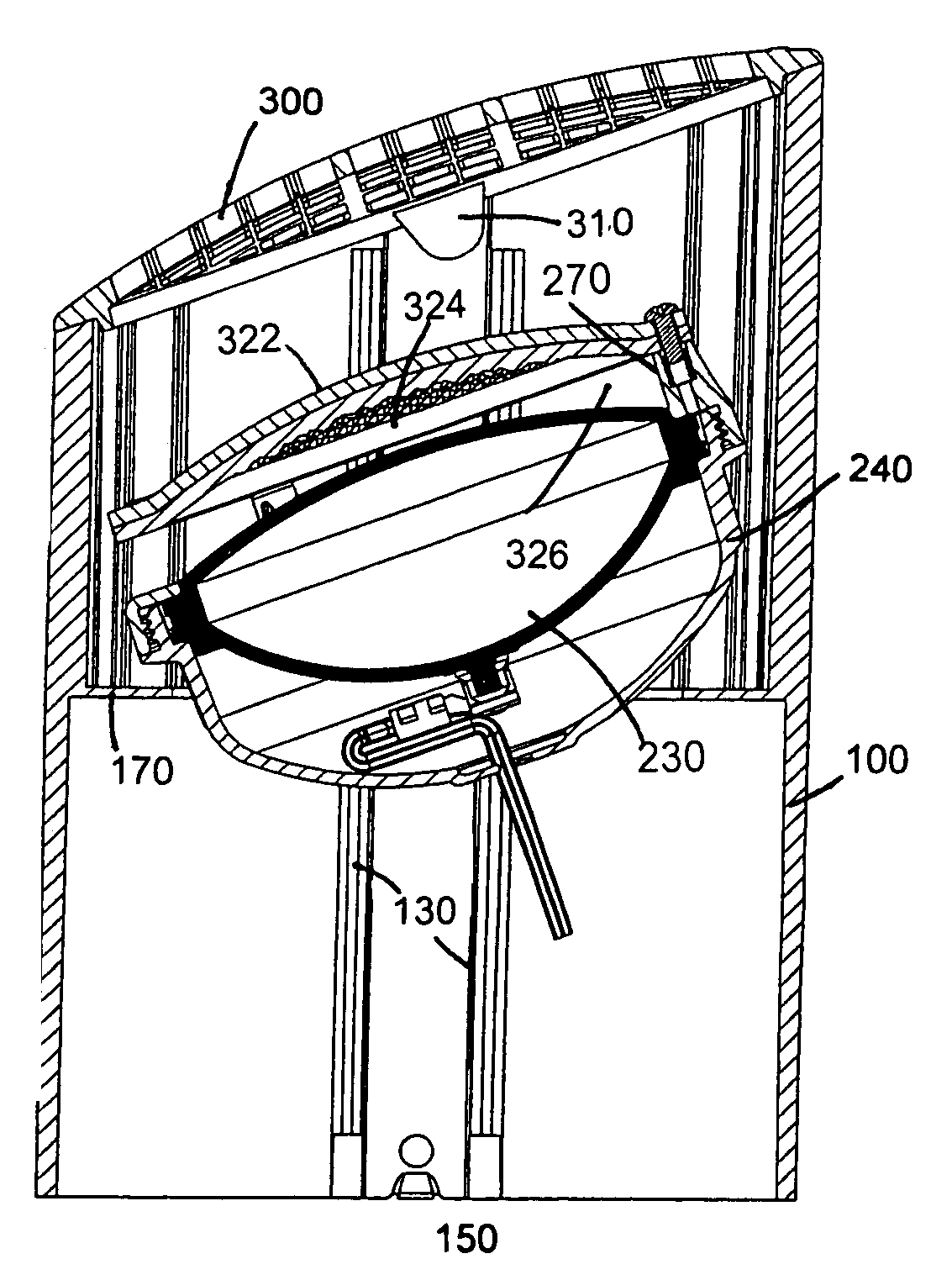
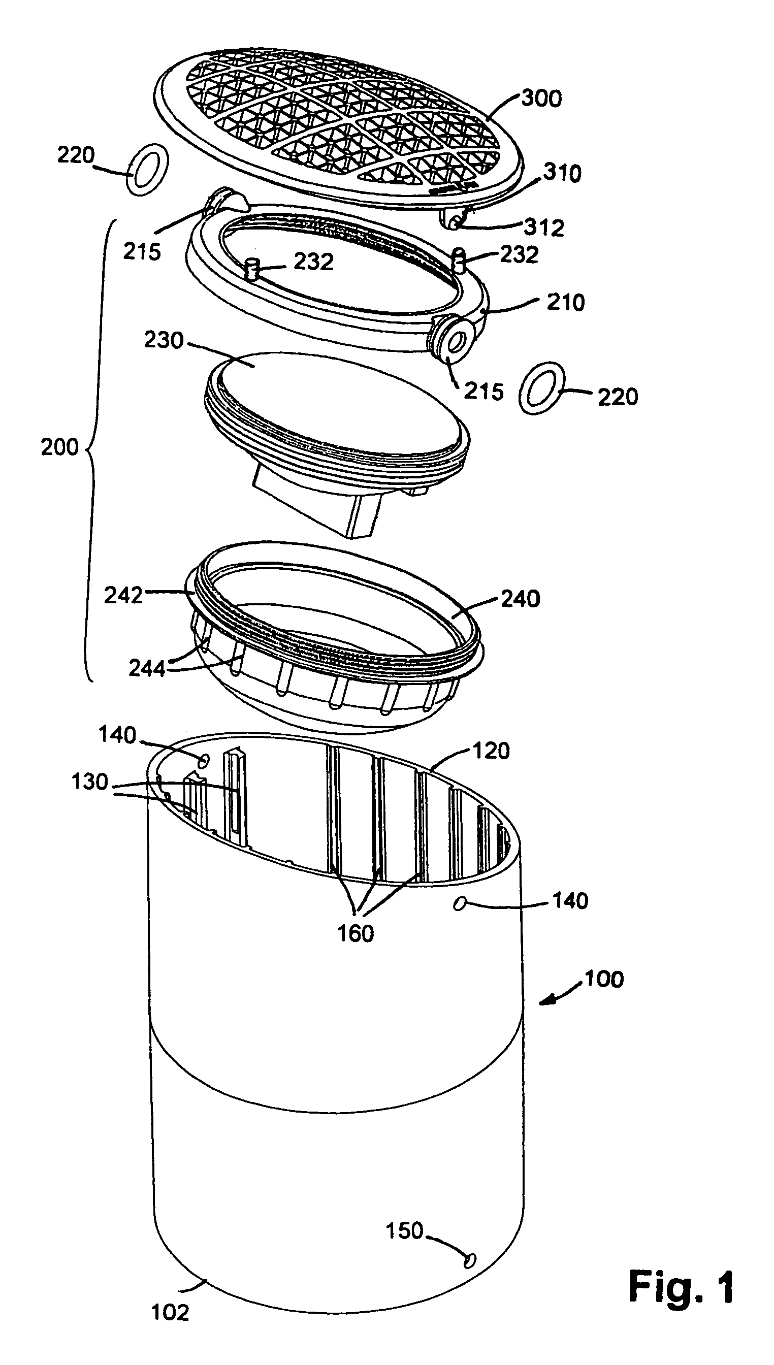
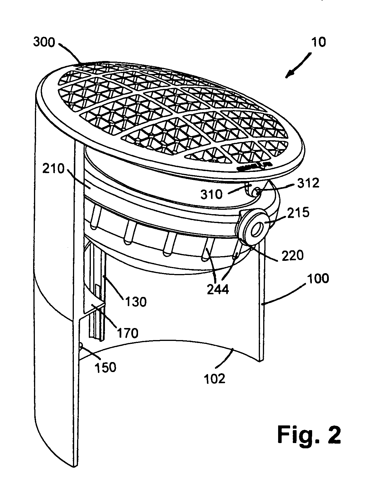
[0026]As illustrated in FIGS. 1-5, the in-ground lighting fixture 10 includes a cylindrical housing 100, a lamp assembly 200, and a light deflector or cover 300.

[0027]The cylindrical housing 100 has a first, flat end 102, a second, angled end 120, an outer diameter, and an inner diameter. Housing 100 may be formed from polyvinylchloride (PVC), polymer, plastic or similar materials that are resistant to corrosion and oxidation. In the preferred embodiment, housing 100 is injection molded from a thermoplastic polyester resin such a Valox®. Two channels 130 extend vertically (longitudinally) at diametrically opposite locations of the inner surface of the housing. Each channel 130 is formed from a pair of rails with arced or shallow C-shaped depressions on their inner faces to define a channel spacing 162, as seen in FIG. 6b, which generally corresponds to the outer diameter of O-ring 220. The channels 130 are preferably formed integrally with the housing, for example, during a injectio...


PUM


Abstract

The in-ground, or “well light”, fixture comprises a hollow cylindrical housing with an angled end and an flat end, a lamp assembly easily mounted at either end, and a baffle. The lamp assembly is rotatably and vertically adjustable within the housing and either the angled end or the flat end may be placed upward by virtue of a pair of channels extending down the length of the housing. Fasteners are provided on the lamp assembly for attaching one or more filters above the lamp face and to create a protective air gap that prevents debris from accumulating on the lamp.

Description

FIELD OF THE INVENTION[0001]The present invention relates to lighting fixtures for landscape and environmental lighting applications and, more particularly, to in-, or below-ground lighting fixtures.BACKGROUND OF THE INVENTION[0002]The use of outdoor lighting fixtures has become increasingly popular for illuminating buildings, gardens, pathways, and entrance ways as the nighttime play of light on the landscape and exterior structures is aesthetically pleasing. Additionally, such lighting provides enhanced security by reducing eliminating dark hiding places and unobserved entry points for intruders. The most widely used outdoor lighting systems include one or more low voltage lighting fixtures that are connected to a 12 V transformer that is, in turn, connected to a standard 120 VAC line. Each lighting fixture generally includes a housing, a lamp assembly having a halogen lamp or conventional bulb and a reflector, and a lens or window. Many configurations are known for providing a va...

Claims


Application Information

Patent Timeline
Patent Type & Authority Patents(United States)
IPC IPC(8): F21V19/02
CPCF21S8/022F21V21/30F21V9/00F21W2131/10F21W2131/109
Inventor BEADLE, JOSHUA Z.
Owner HUNTER INDUSTRIES
Why Eureka
Try Eureka