
Method and apparatus for radiation detection in a high temperature environment

a radiation detection and high temperature environment technology, applied in the field of radiation detection methods and apparatuses, can solve the problems of not being able to eliminate gaps completely, all of these approaches suffered from one or more limitations, and the photons created in the scintillation process are abated

Inactive Publication Date: 2008-01-22
SCHLUMBERGER TECH CORP
View PDF14 Cites 14 Cited by
  • Summary
  • Abstract
  • Description
  • Claims
  • Application Information

AI Technical Summary

Benefits of technology

This design significantly reduces photon loss, enhances sensitivity, and allows reliable operation in high temperature and noisy environments by ensuring compatibility and stability of the scintillating and photocathode materials, effectively addressing the limitations of prior detectors.

Problems solved by technology

One problem with conventional scintillation-type radiation detectors is the fact that at each of the couplings, photons created in the scintillation process are abated because of a mismatch in the indices of refraction or because of absorption.
All of these approaches suffered from one or more limitations.
While the decrease in the size of the interface gaps is helpful, it is not possible to eliminate gaps entirely.
As such, photons continue to be lost in traversing gaps and coupling agents.
Window design entails compromises and direct deposit applications have not been useful in high temperature environments.
Downhole applications, however, present a challenge because of the temperature at which the radiation detector must operate and the fact that increased vibration may affect the integrity of the interfaces between components
The difficulties and limitations suggested in the preceding are not intended to be exhaustive, but rather are among many which demonstrate that although significant attention has been devoted to increasing efficiency and sensitivity in scintillating type radiation detectors, the prior attempts do not satisfy both the desired increase in efficiency and the need for operation in noisy, high temperature environments.

Method used


Image

  • Method and apparatus for radiation detection in a high temperature environment
  • Method and apparatus for radiation detection in a high temperature environment
  • Method and apparatus for radiation detection in a high temperature environment

Examples


Embodiment Construction

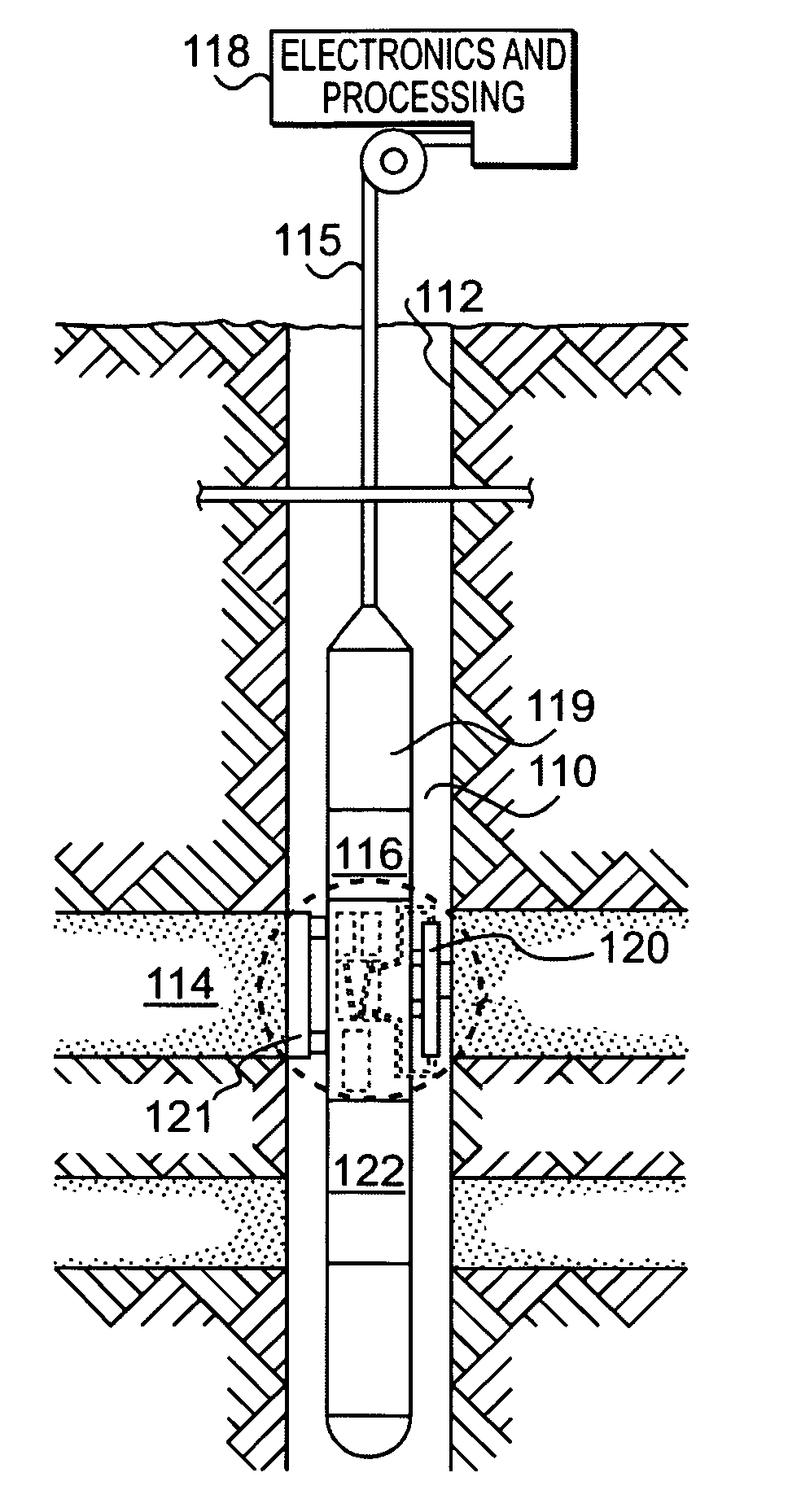
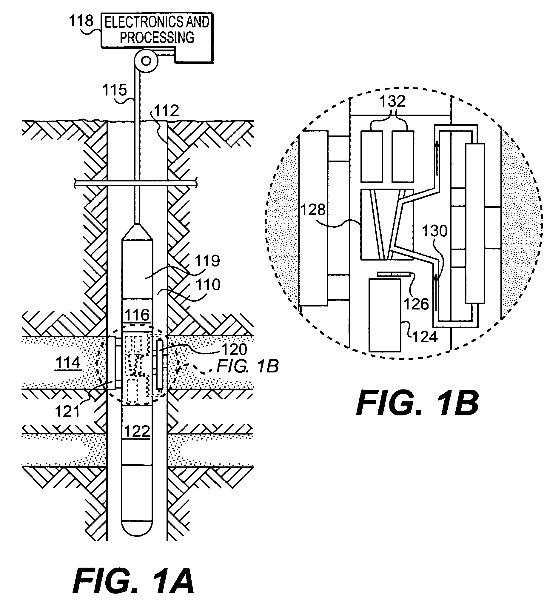
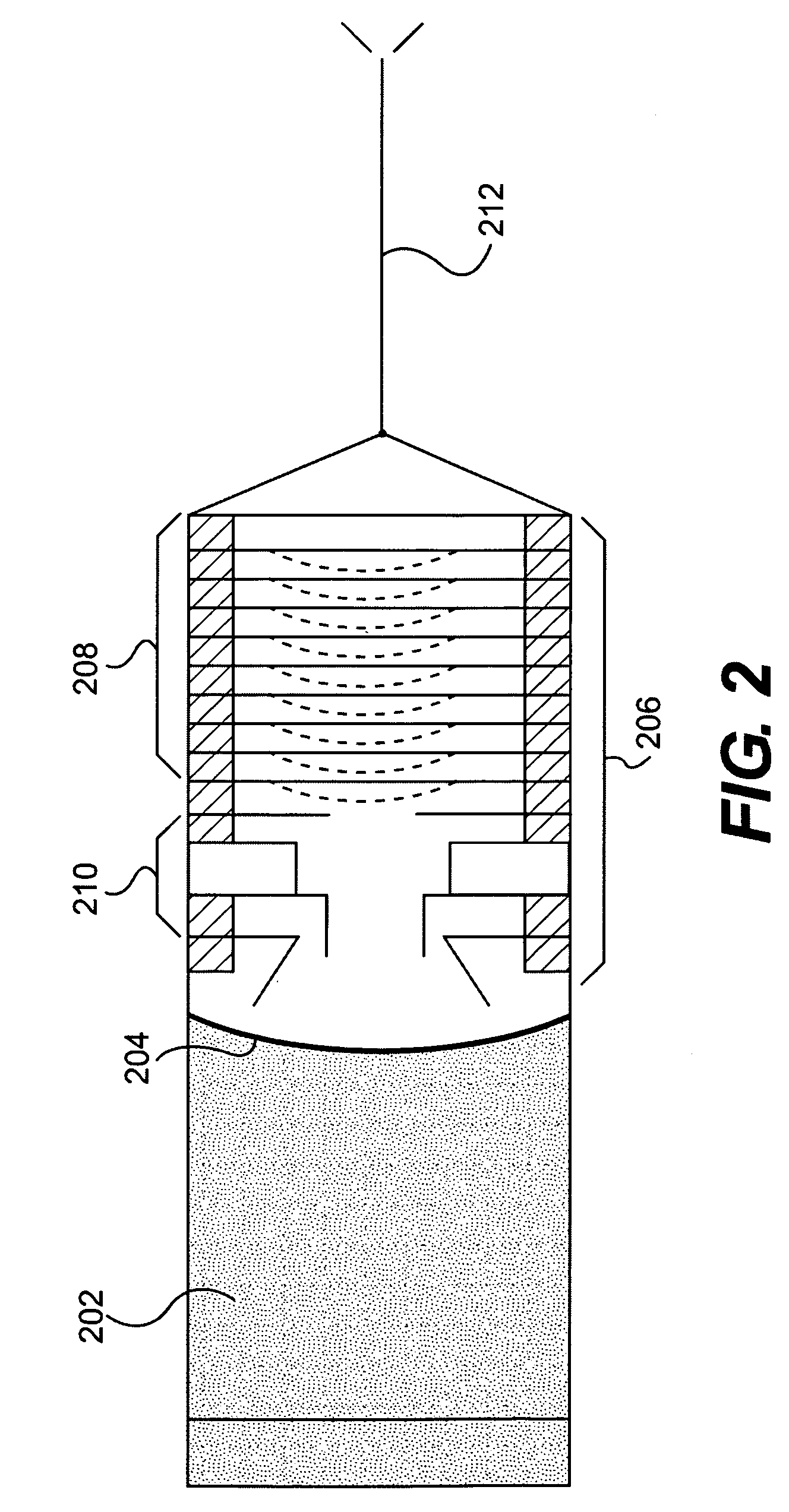
[0009]A preferred embodiment of the invention comprises a method and apparatus for measuring radiation in a high temperature environment. In a preferred embodiment, a photocathode is deposited directly onto a concave surface of a scintillating material. This surface is oriented toward an electron multiplier comprising focus electrodes and a dynode stack. Radiation incident on the scintillating material causes it to generate light, when this light comes into contact with the photocathode, electrons are output that are then amplified by the electron multiplier and output on a wire for measurement.

THE DRAWINGS

[0010]Objects and advantages of the present invention will become apparent from the following detailed description of embodiments taken in conjunction with the accompanying drawings, wherein:

[0011]FIG. 1A is a schematic view of the context in which the present invention can be used to advantage.

[0012]FIG. 1B is an expanded schematic view of a scintillator system for measuring dens...


PUM


Abstract

A radiation detector operating at high temperatures is shown comprising a LuAP scintillating material for producing light when excited by incident radiation, a photocathode, and an electron multiplier. The photocathode is deposited directly onto the surface of the scintillating material that is oriented toward the electron multiplier. In a preferred embodiment, a metal flange is hermetically sealed to the scintillating material and this is fusion welded to the electron multiplier to create a vacuum envelope. This invention is particularly useful in high temperature noisy environments such as downhole operations to detect radiation within a well hole.

Description

BACKGROUND OF THE INVENTION[0001]This invention relates to a method and apparatus for radiation detection. More specifically, this invention relates to a method and apparatus for radiation detection in a high temperature environment.[0002]The detection of radiation through the use of scintillating material has been successfully employed in the past in a variety of contexts. In this, light is produced by a scintillating material in response to incident radiation. This light is operably converted to an electrical signal through the use of a photomultiplier (“PMT”) and this electrical signal can be used to determine the amount and strength of the incident radiation.[0003]In conventional radiation detectors utilizing scintillating material, the scintillating material and PMT are usually two separate components. Each is fabricated independently and they are brought together at a final stage of construction. The common practice in creating this type of detector is to first cut and polish ...

Claims


Application Information

Patent Timeline
Patent Type & Authority Patents(United States)
IPC IPC(8): G01T1/20G01T1/24
CPCG01T1/20G01T1/28
Inventor SIMONETTI, JOHNGROVES, JOEL L.ZIEGLER, WOLFGANGLIBERMAN, ARTSTOLLER, CHRISTIAN
Owner SCHLUMBERGER TECH CORP
Learn More