Sensorless brushless direct current motor drive using pulse width modulation speed control at motor frequency

a motor drive and pulse width modulation technology, applied in the direction of motor/generator/converter stopper, electronic commutator, dynamo-electric converter control, etc., can solve the problems of low switch efficiency loss when operated at motor frequency, and reduce the time of igbts to conduct electricity, so as to reduce the conduction loss and low the effect of loss of low switch efficiency

Active Publication Date: 2008-01-22
INFINEON TECH AMERICAS CORP
View PDF10 Cites 8 Cited by
  • Summary
  • Abstract
  • Description
  • Claims
  • Application Information

AI Technical Summary

Benefits of technology

[0007]A BLDC drive circuit of the present invention combines the best features of the six-step trapezoidal drives and the PWM drives. Thus, the features of the BLDC drive circuit of the present invention include (a) a very low switch conduction loss of the six step drives and (b) a PWM of an AC output without the need for high frequency IGBT switches. Moreover, these features enable the inventive BLDC drive circuit to use standard speed IGBTs that have lower conduction losses and low switch efficiency losses when operated at motor frequency. Additionally, the BLDC drive circuit of the present invention maximizes the resulting overall drive efficiency.
[0009]Instead of driving the IGBTs directly, the inventive BLDC drive circuit outputs trigger a delay that causes the IGBTs to conduct electricity for a reduced time at each commutation of the motor. By reducing the IGBTs' conduction time, the BLDC drive circuit effectively reduces the volt-seconds output and thus, controls the motor speed.

Problems solved by technology

Moreover, these features enable the inventive BLDC drive circuit to use standard speed IGBTs that have lower conduction losses and low switch efficiency losses when operated at motor frequency.
Instead of driving the IGBTs directly, the inventive BLDC drive circuit outputs trigger a delay that causes the IGBTs to conduct electricity for a reduced time at each commutation of the motor.

Method used


Image

  • Sensorless brushless direct current motor drive using pulse width modulation speed control at motor frequency
  • Sensorless brushless direct current motor drive using pulse width modulation speed control at motor frequency
  • Sensorless brushless direct current motor drive using pulse width modulation speed control at motor frequency

Examples


Embodiment Construction

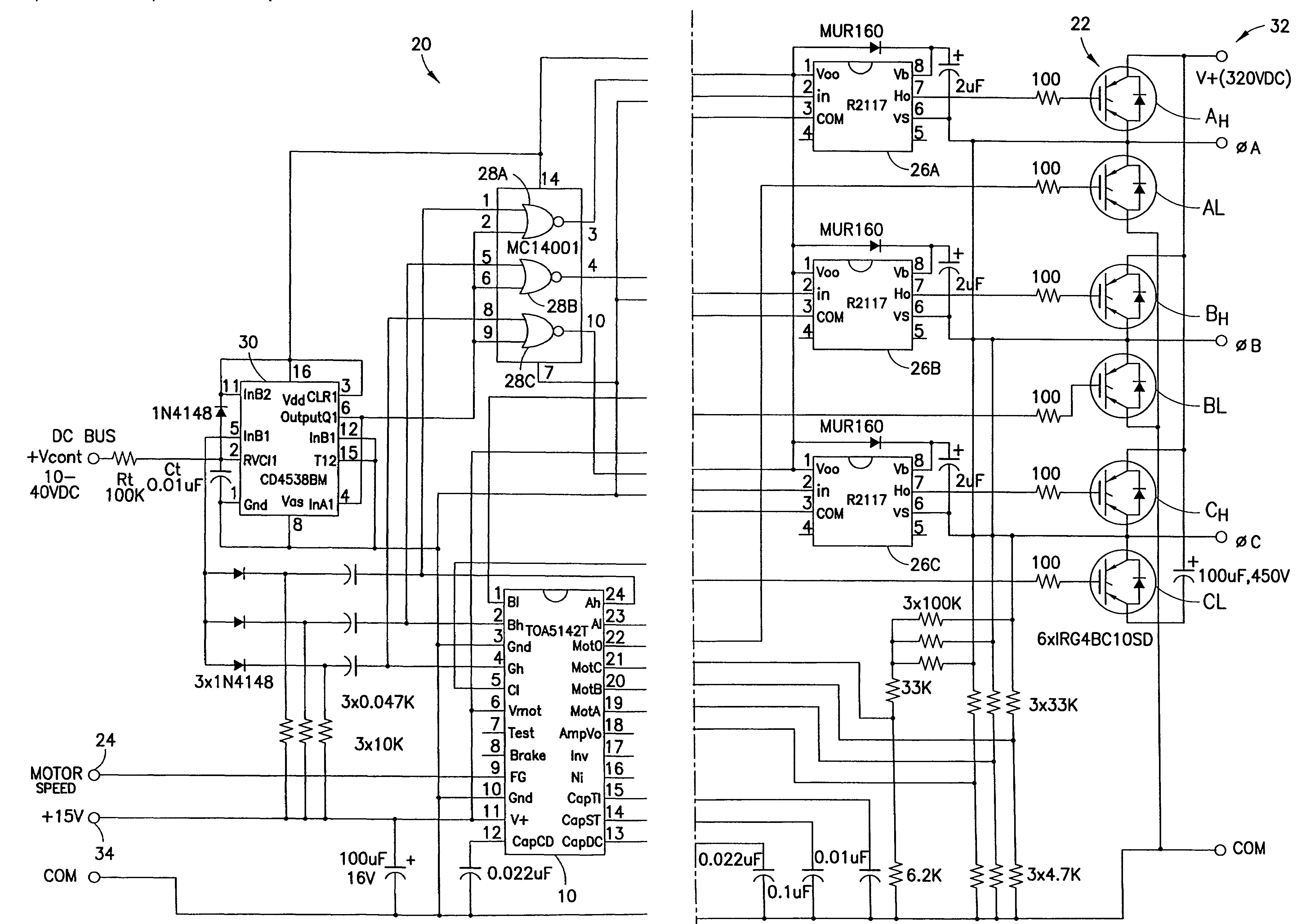
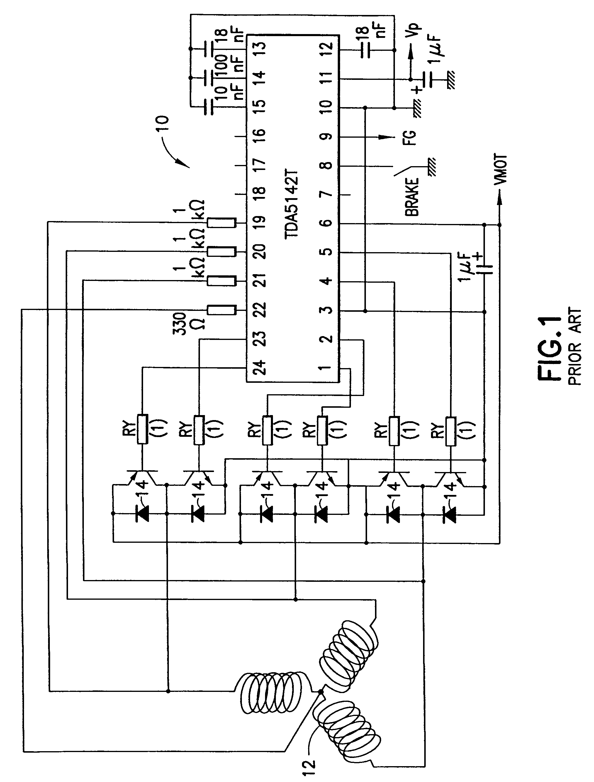
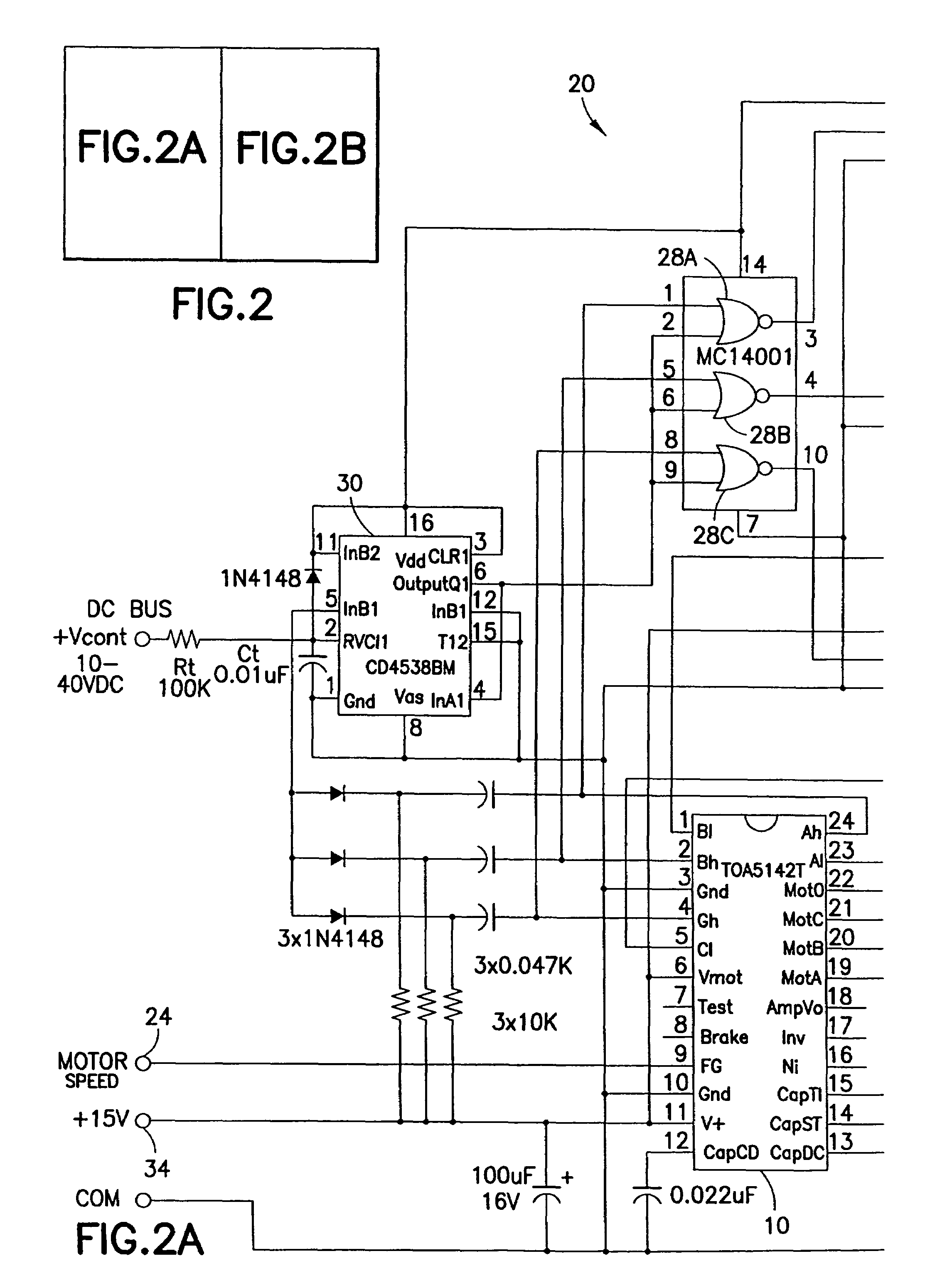
[0021]FIG. 1 illustrates a typical three-phase 300-Watt brushless direct current (BLDC) motor drive integrated circuit (IC)10 used for various applications, including refrigeration. A microprocessor or digital signal processor (DSP) may be used to generate pulse width modulation (PWM) of the output signals at pins 1, 2, 4, 5, 23, and 24 of the BLDC motor drive IC 10. These PWM signals are used to drive power insulated gate bipolar transistors (IGBTs) 14, which provide power for starting and running a motor 12. The PWM frequency for such three-phase BLDC motor drive ICs 10 is chosen as a compromise between the need for minimum waveform distortion and minimum electromagnetic interference / radio frequency interference (EMI / RFI) generation and usually lies somewhere between 4 KHz and 16 KHz.

[0022]Six-step drives, on the other hand, operate motors at frequencies which are usually in the range of 40 to 300 Hz and speed regulation is achieved by direct current (DC) bus voltage control which...


PUM


Abstract

Disclosed is a variable speed brushless direct current (BLDC) motor drive circuit. The circuit includes a plurality of high-side and low-side controlled switches coupled in a three-phase bridge configuration for commutating a BLDC motor, each phase of the bridge being connected to a corresponding phase of the motor, a controller for providing a drive signal to drive each of the high-side and low-side switches, and a speed control loop for controlling the motor by PWM of a DC bus voltage to achieve a constant motor speed. The speed control loop includes a pulse circuit receiving the drive signals provided from the controller for controlling the high-side switches and for providing a pulse signal that is related to a desired motor speed, a plurality of high-side drivers for driving the high-side switches, each high-side switch being coupled to a respective high-side driver, and a plurality of gating circuits each receiving the pulse signal from the pulse circuit and a drive signal for a respective high-side controller from the controller for generating a pulse width modulation (PWM) control signal having a pulse duration determined by said pulse signal from said pulse circuit to thereby drive each of the high-side drivers to modulate their corresponding high-side switches.

Description

CROSS-REFERENCE TO RELATED APPLICATION[0001]This application is based on and claims benefit of U.S. Provisional Application Ser. No. 60 / 668,897, filed on Apr. 5, 2005, entitled SENSORLESS BRUSHLESS DC MOTOR DRIVE USING PULSE WIDTH MODULATION SPEED CONTROL AT MOTOR FREQUENCY, to which a claim of priority is hereby made and the disclosure of which is incorporated by reference.FIELD OF THE INVENTION[0002]The present invention relates to brushless direct current (BLDC) motor drives, and more particularly, to minimizing switch losses in three-phase pulse width modulation (PWM) BLDC motor drives.BACKGROUND OF THE INVENTION[0003]Typically, two distinct types of drives, six-step trapezoidal drives and PWM drives, are used to drive multi-phase BLDC motors. In the six step trapezoidal drives, speed regulation is obtained by controlling a direct current (DC) supply voltage with a pre-regulator operating at a high frequency. In the PWM drives, the speed regulation is obtained by controlling a v...

Claims


Application Information

Patent Timeline
Patent Type & Authority Patents(United States)
IPC IPC(8): H02P1/18
CPCH02P6/085H02P6/14H02P6/182H02P2209/07
Inventor WOOD, PETER N
Owner INFINEON TECH AMERICAS CORP
Why Eureka
Try Eureka