Optical fibre amplifier

a technology of optical fiber amplifier and fiber, which is applied in the field of fiber amplifier, can solve the problems of limiting the optical power that can be coupled into the fibre, difficult and expensive manufacturing of fibres, and limited bandwidth of multi-mode optical fibre based systems

Active Publication Date: 2008-01-22
QINETIQ LTD
View PDF31 Cites 6 Cited by
  • Summary
  • Abstract
  • Description
  • Claims
  • Application Information

AI Technical Summary

Benefits of technology

[0009]It is an object of the present invention to mitigate at least

Problems solved by technology

Multi-mode optical fibre based systems typically have a limited bandwidth due to modal dispersion effects within the fibre.
Although modal dispersion effects can be reduced or eliminated by using parabolically graded index multimode fibres and the like, such fibres are difficult and expensive to manufacture.
However, the small core diameter (typically less than 10 μm) that is required

Method used


Image

  • Optical fibre amplifier
  • Optical fibre amplifier
  • Optical fibre amplifier

Examples


Embodiment Construction

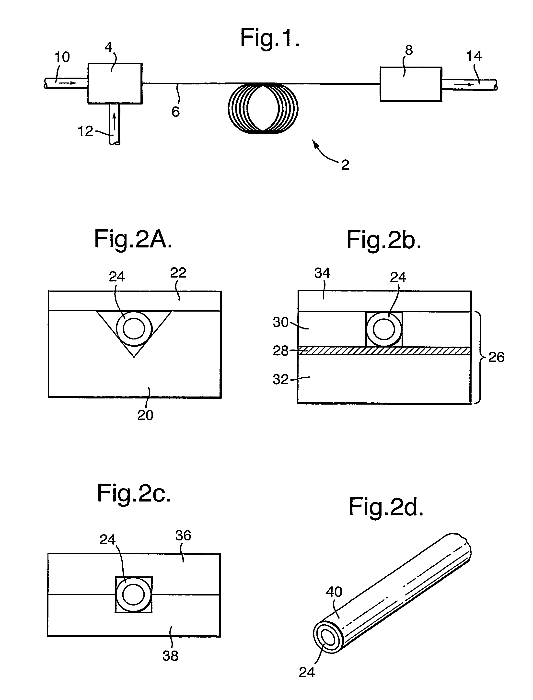
[0067]Referring to FIG. 1, a prior art erbium doped fibre amplifier 2 is illustrated. The amplifier 2 comprises an input stage 4, an erbium doped single mode optical fibre 6 and an output stage 8. The erbium doped optical fibre 6 is around ten metres long, and is typically arranged in a loose coil of several centimeters in radius.

[0068]The input stage 4 is arranged to couple a signal beam from an input single mode optical fibre 10 and an incident pump beam 12 into the erbium doped single mode optical fibre 6. The pump beam 12 causes the signal beam to be amplified within the erbium doped optical fibre 6, and the amplified signal beam is received by the output stage 8 and coupled into an output single mode optical fibre 14 for onward transmission.

[0069]As described above, single mode optical fibres used in known EDFAs have a small core diameter (several microns only). This small core diameter means long lengths of single mode optical fibre are necessary to achieve the required gain. ...


PUM


Abstract

An optical amplifier is described that comprises at least two sections of amplifying optical fibre and pumping means for optically pumping the amplifying optical fibre. Optical fibre support means, for example a channel or channels in a substrate, are also provided to hold the two or more sections of amplifying optical fibre substantially straight during use. The optical fibre support means also includes a means for coupling light between the at least two sections of amplifying optical fibre. The at least one amplifying optical fibre may comprise an Erbium doped core to provide an erbium doped fibre amplifier (EDFA).

Description

BACKGROUND OF THE INVENTION[0001](1) Field of the Invention[0002]The present invention relates to a fibre amplifier, and more particularly to an erbium doped fibre amplifier (EDPA).[0003](2) Description of the Art[0004]Optical fibre based networks are known and have been implemented in many forms using both single mode and multi-mode optical fibres. Multi-mode optical fibre based systems typically have a limited bandwidth due to modal dispersion effects within the fibre. Although modal dispersion effects can be reduced or eliminated by using parabolically graded index multimode fibres and the like, such fibres are difficult and expensive to manufacture. Multi-mode optical fibres are thus typically only used in low speed network applications.[0005]Modal dispersion effects are, by definition, insignificant in single mode optical fibres and such fibres are thus used in high bandwidth data transmission systems. However, the small core diameter (typically less than 10 μm) that is require...

Claims


Application Information

Patent Timeline
IPC IPC(8): H01S3/00G02B6/26H01S3/067H01S3/094
CPCH01S3/06704H01S3/06758H01S3/094042H01S3/094053H01S3/1608
Inventor JENKINS, RICHARD M.MCNIE, MARK E.PRICE, NICOLASTACEY, CRAIG D.
Owner QINETIQ LTD
Why Eureka
Try Eureka