Compact optical sub-assembly

a sub-assembly and optical technology, applied in the field of compact optical sub-assembly, can solve the problems of limiting the quality of transmission and positioning of the transceiver pcb, affecting the quality of the signal integrity of the device, and so as to achieve the effect of reducing the width of the housing

Active Publication Date: 2008-01-29
LUMENTUM OPERATIONS LLC
View PDF9 Cites 34 Cited by
  • Summary
  • Abstract
  • Description
  • Claims
  • Application Information

AI Technical Summary

Benefits of technology

[0015]a rear beam steering lens for redirecting the portion of the light from the laser axis back towards the longitudinal optical axis, and for focusing the portion of the light onto the monitor photo-detector, thereby enabling the width of the housing to be reduced.

Problems solved by technology

The Cina et al device will suffer from poor signal integrity at high data transfer rates, because the RF signals need to transmit through the leads 23 and 24, which limits the quality of the transmission and the positioning of the transceiver PCB.
Moreover, the Arvanitakis et al device does not disclose the use of controlled signal impedance conductors required for high-quality high-data rate signals.
Unfortunately, none of these solutions are suitable for TOSA designs, particularly TOSA applications with back facet monitor photodiodes.

Method used


Image

  • Compact optical sub-assembly
  • Compact optical sub-assembly
  • Compact optical sub-assembly

Examples


Embodiment Construction

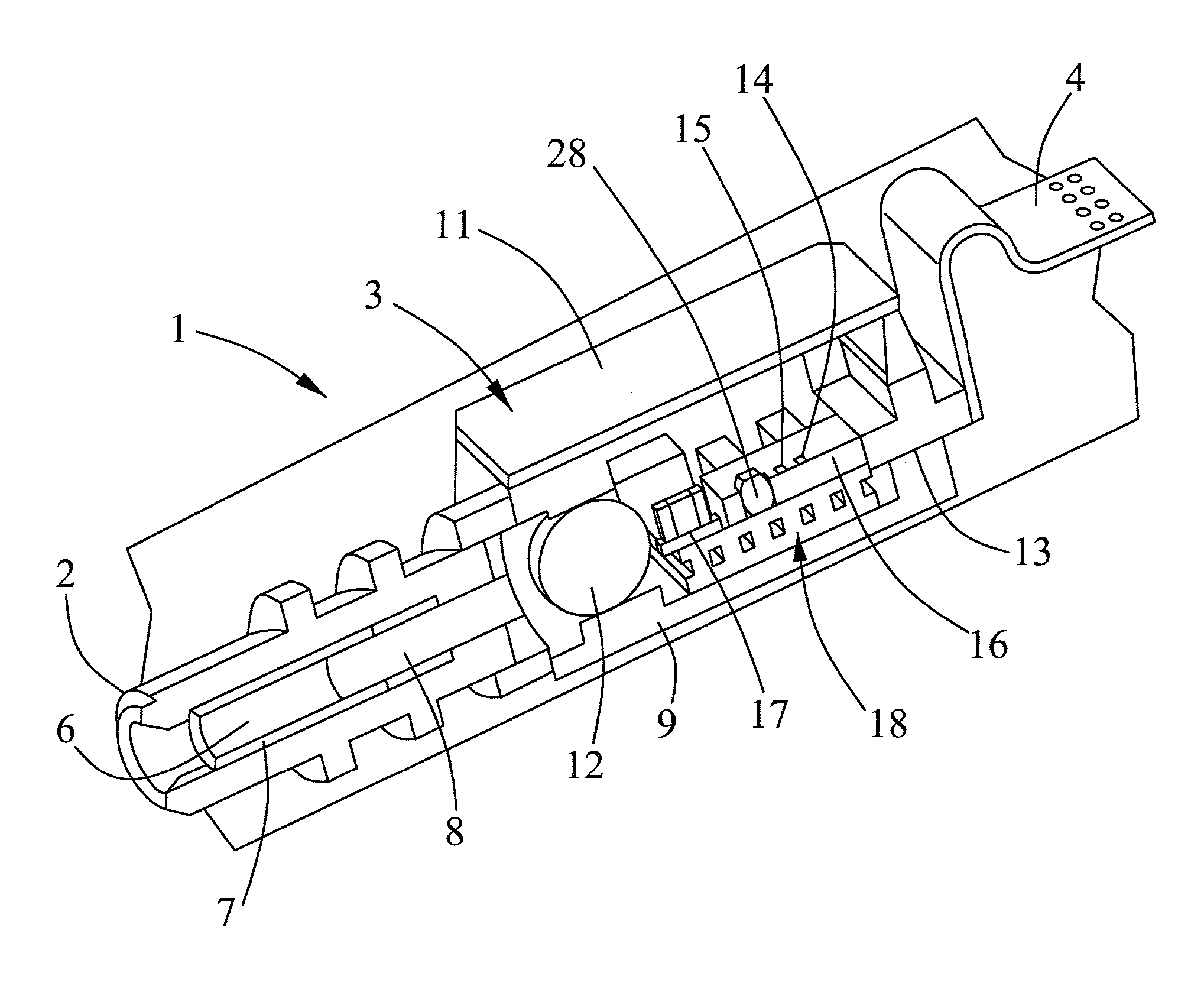
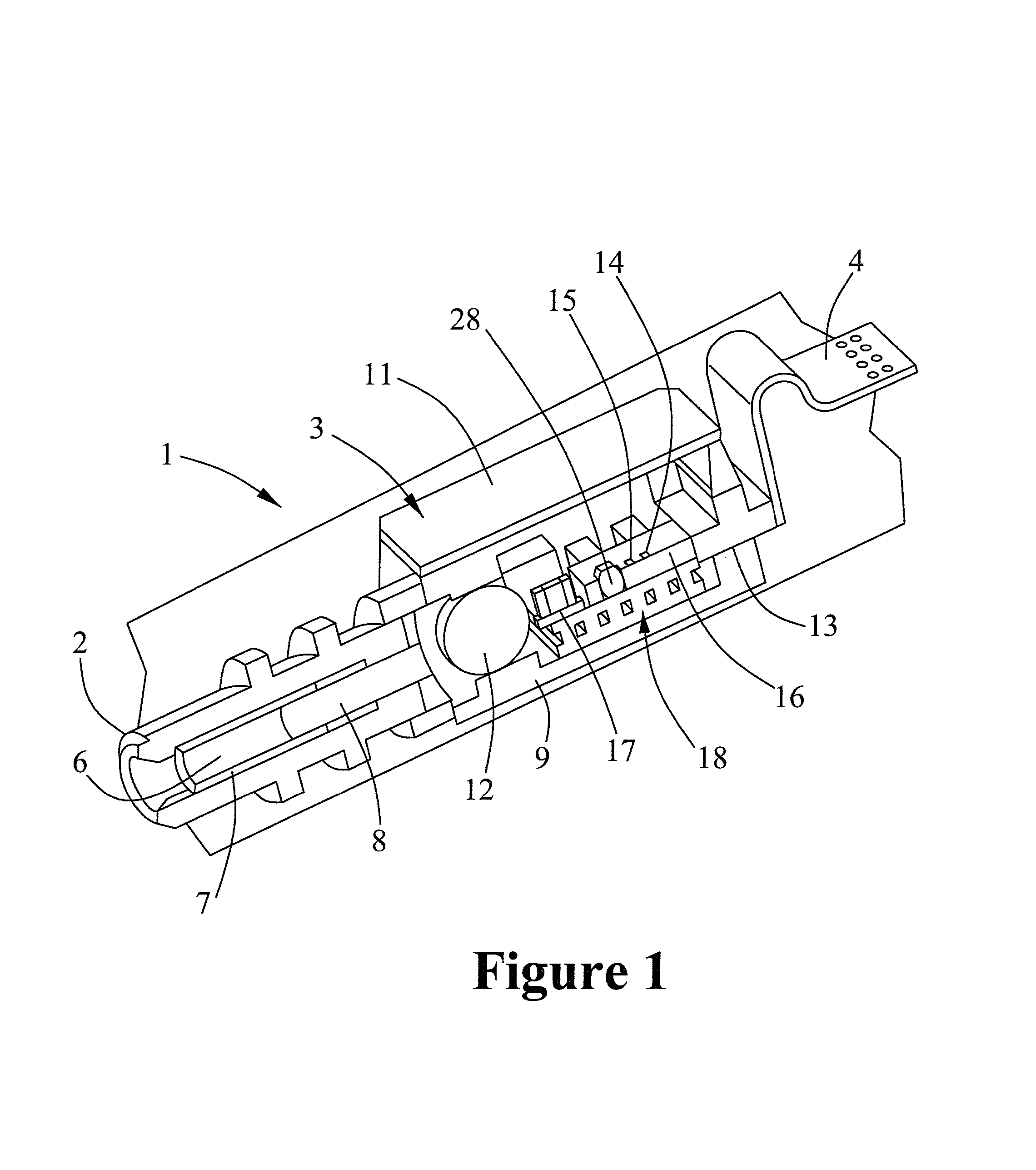
[0029]With reference to FIGS. 1 to 4, a transmitter optical sub-assembly (TOSA) according to the present invention, generally indicated at 1, includes an optical coupler 2, a main housing 3, and an electrical connector 4. The optical coupler 2 defines a bore 6 with a zirconia split sleeve 7 therein for receiving an optical fiber ferrule mounted on the end of an optical fiber, preferably fitted into an LC optical connector, as is well known in the art. An angle polished ferrule 8 is mounted in the optical coupler 2 for transmitting light from the housing to the optical fiber along a main optical axis OA.

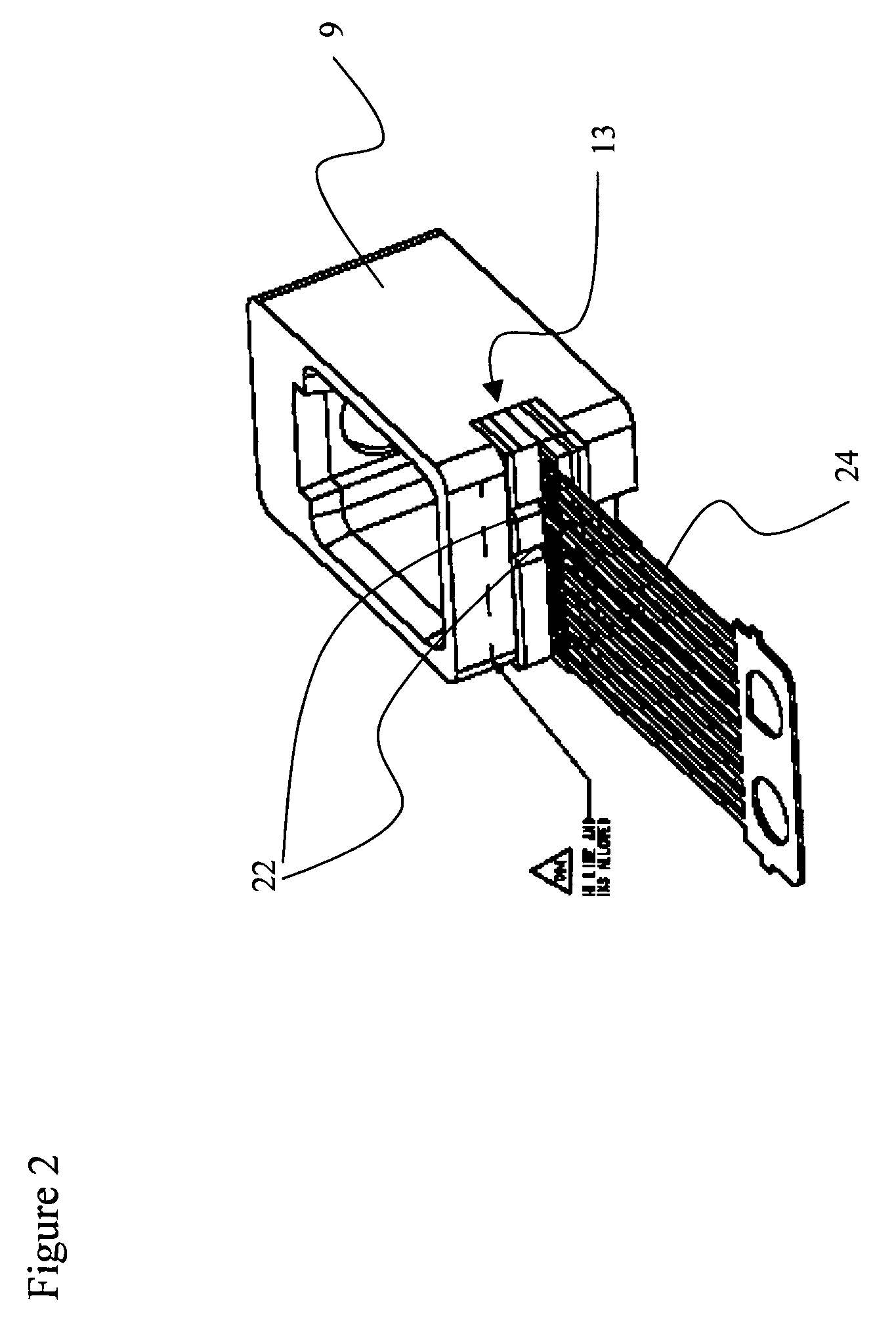
[0030]Preferably, the main housing 3 is comprised of a metal injection molded (MIM) hermetic package 9 with a lid 11, comprised of a material with a relatively low coefficient of thermal expansion, e.g. Kovar, although any suitable construction method and material can be used. A focusing lens 12 hermetically seals the front or optical end of the housing 3, while a multi-layer ceramic ...


PUM


Abstract

The invention relates to a compact transmitter optical sub-assembly (OSA), which can be used in small form factor optical transceivers. To limit back reflections from entering the laser cavity, the laser is disposed on a silicon optical bench (SiOB) at an acute angle to the longitudinal axis of the OSA. A portion of the light from the laser cavity passes through the back end of the laser cavity for measuring by a monitor photodiode. A rear beam steering lens redirects the portion of light into a v-groove in the SiOB and off of a reflective surface formed in the end thereof to the monitor photodiode, which is positioned face down over the v-groove.

Description

CROSS-REFERENCE TO RELATED APPLICATIONS[0001]The present invention claims priority from U.S. patent application Ser. No. 60 / 543,726 filed Feb. 11, 2004, which is incorporated herein by reference.TECHNICAL FIELD[0002]The present invention relates to a compact optical sub-assembly (OSA), and in particular to a transmitter optical sub-assembly (TOSA) including a light source mounted at an angle to the output axis.BACKGROUND OF THE INVENTION[0003]The driving forces in the transceiver manufacturing industry are reducing the form factor sizes, increasing the data transfer rates, and decreasing the costs. To achieve all of these goals, the conventional butterfly-type or transistor outline (TO) can design approach must be replaced with a more exotic component packaging approach. However, to provide an OSA that can be used over a wide range of data transfer rates and products, the OSA must use controlled impedance connections for the high speed RF electrical signal path between the OSA chip ...

Claims


Application Information

Patent Timeline
Patent Type & Authority Patents(United States)
IPC IPC(8): G02B6/42G02B6/36
CPCG02B6/4214G02B6/4246
Inventor WOLF, ROBERT K.FU, HUIYESENOFSKI, ANTHONY T.HART, CHRISMAO, ERJIBUKKEMS, HEINOHOGAN, WILLIAM K.
Owner LUMENTUM OPERATIONS LLC
Why Eureka
Try Eureka