Eureka AIR delivers breakthrough ideas for toughest innovation challenges, trusted by R&D personnel around the world.

Belt drive propulsion system

a belt drive and propulsion system technology, applied in marine propulsion, vessel construction, transportation and packaging, etc., can solve the problems of increasing the need to move the vessel exponentially, and the belt drive system can require lower horsepower at higher speeds, so as to improve the efficiency of the belt drive, reduce parasitic friction, and increase the speed

Active Publication Date: 2008-01-29
FOI GRP
View PDF4 Cites 1 Cited by
  • Summary
  • Abstract
  • Description
  • Claims
  • Application Information

AI Technical Summary

Benefits of technology

[0009]Unlike other belt drive systems, this system reduces parasitic friction by having minimal relative velocity between the belt and the engaged water and by preventing the belt drive from being excessively submerged. This second feature greatly improves the efficiency of the belt drive because if the belt drive were submerged below the lower horizontal portion of the drive, it would generate significant vertical forces and turbulence, and if the top portion were submerged, substantial counteracting horizontal forces would be produced as the upper part of the belt would be propelling the water in the opposite direction. Such reduction in counter productive forces and turbulence allows vessels using this drive to achieve much higher rates of speed at greater efficiency levels than are possible using current propulsion methods.
[0010]Horizontal linear air bearing surfaces between the drive pulleys allow the belt to transmit vertical loads while it moves with minimal resistance, although water lubricated slides or rollers may also be used. The drive units can also be suspended in open-bottomed enclosures that create a more stable adjustable water level below the surrounding water conditions, which produces lift equal to the water displaced and allows the belt drives to engage the water in the relatively calm conditions inside the enclosure. The pressurized enclosures also provide for floatation when the vessel is stationary or traveling at low speeds with supplemental flotation compartments providing redundancy and long term floating storage capacity. Discharged air from the linear air bearings both pressurizes the enclosure and is vented through ports in lower perimeter of the enclosure to create a layer of air bubbles along the walls of the enclosure that act to reduce friction drag. There is no significant friction between the air-water boundary inside the enclosure so hull friction is lowered relative to a full-bodied vessel, because of the sharp reduction in wetted hull surface. This advantage also allows wider cross-section vessels which increases stability. Therefore, unlike traditional vessel designs, in which the power necessary to move the vessel increases exponentially with speed, the belt drive system can require lower horsepower at higher speeds. As the speed increases, the effective load carrying capacity of the water surface increases. Low surface pressure vessels can be supported entirely by the belt drives at high speed, thereby eliminating hull water friction. Even at lower speeds hull friction is reduced as the belt drive is able to transmit more load to the water surface. In that situation, the vehicle will reduce the required water displacement needed for flotation. Just as traditional hulls rise out of the water, so the enclosures can be shape to minimize wetted hull area if desired.

Problems solved by technology

Therefore, unlike traditional vessel designs, in which the power necessary to move the vessel increases exponentially with speed, the belt drive system can require lower horsepower at higher speeds.

Method used


Image

  • Belt drive propulsion system
  • Belt drive propulsion system
  • Belt drive propulsion system

Examples


Embodiment Construction

[0019]This invention provides propulsion for naval vehicles through the use of one or more suspended belt drives that utilize flexible belts with multiple attachments or variable lugs to meet changing conditions and requirements.

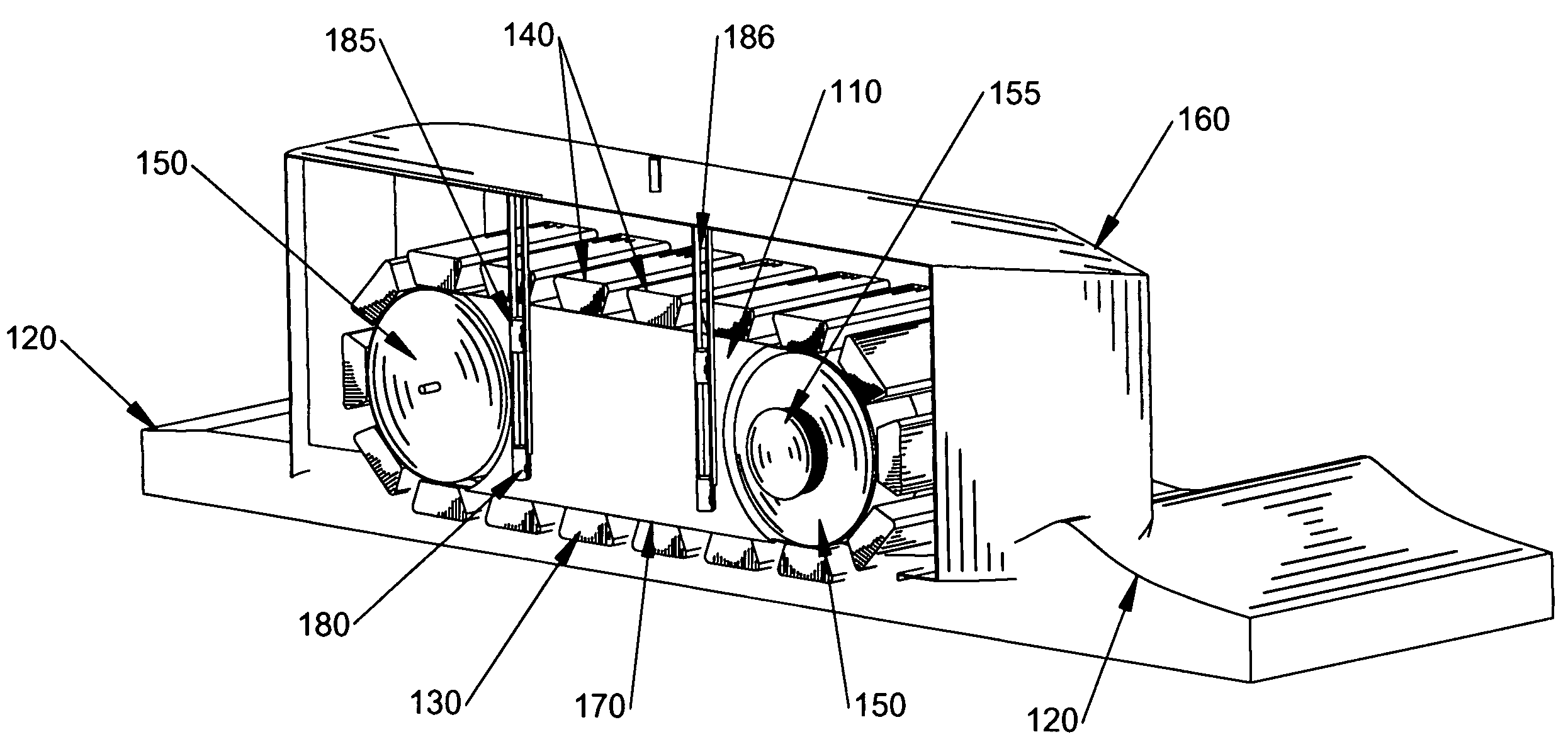
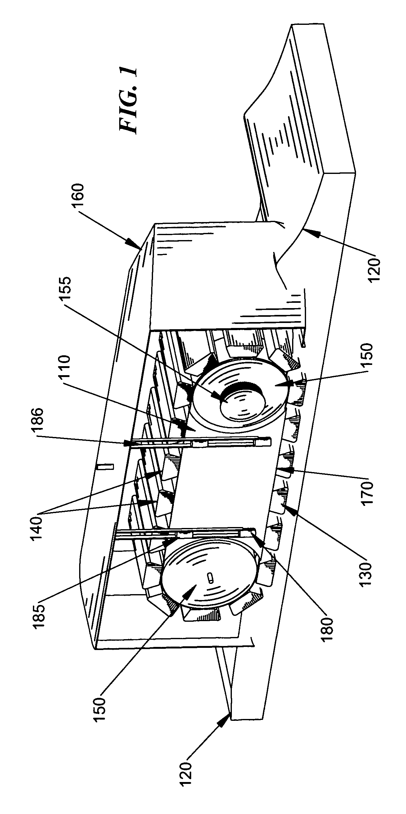
[0020]In one embodiment, as shown in FIG. 1, the belt drive 110 engages the water just above the water surface 120. The flexible belt 130 rotates between dual drive pulleys 150. The belt drive 110 is suspended within the open-bottomed enclosure 160, a feature that allows the drive to move up and down in order to maintain contact between the traction pads 140 and the water surface 120 and to prevent the belt drive from becoming completely submerged below the water surface. Only the force-transferring components of the belt travel below the surface of the water.

[0021]One objective of the invention is to minimize friction by having minimal relative velocity between the belt and the water surface. Friction is further decreased by preventing any unnecessary subme...


PUM


Abstract

An apparatus and method for providing propulsion to naval vehicles by using one or more suspended belt drives to consistently engage the water proximate to the surface using a variety of belts with multiple attachments, tires, or variable lugs. The drive belt system incorporates the use of a linear air bearing surface to minimize the belt friction of the drives. This invention also involves the use of open-bottomed enclosures to insulate the propulsion system from adverse water conditions that might otherwise prevent the belt drives from consistently and efficiently engaging the water.

Description

RELATED APPLICATION DATA[0001]This application claims the benefit of U.S. Provisional Application No. 60 / 726,974 filed Oct. 14, 2005.TECHNICAL FIELD OF THE INVENTION[0002]An apparatus and method for providing a means of propulsion for boats, amphibious vehicles, and other watercraft by using one or more suspended belt drive units that directly engage the water near the surface.BACKGROUND OF THE INVENTION[0003]While there is much prior art regarding marine propulsion and transport, propulsion systems for boats have yet to progress beyond the use of propellers, which remain the primary drive for naval vessels. Even the ideal propeller is still an inefficient device and the traditional vessel hull requires rapid increases in power as speed rises. A small pleasure ski boat at 30 mph gets the same fuel economy as a semi truck on the highway. Even modern propellers can have significant cavitation-producing slippage, especially during acceleration. Design characteristics of propellers prev...

Claims


Application Information

Patent Timeline
IPC IPC(8): B60F3/00
CPCB60F3/0015B63H1/34
Inventor MUNSON, JR., DAVID MURRAY
Owner FOI GRP
Why Eureka
Eureka Blog
Learn More