Infrared gas analyzer and infrared gas analysis method
a gas analyzer and infrared technology, applied in the field of infrared gas analyzers, can solve the problems of not being able to fully get the advantage of the light source, and proposing a configuration of an analyzer suitable for use, and achieves the effects of high precision, excellent thermal responsiveness, and simple configuration
- Summary
- Abstract
- Description
- Claims
- Application Information
AI Technical Summary
Benefits of technology
Problems solved by technology
Method used
Image
Examples
embodiment 1
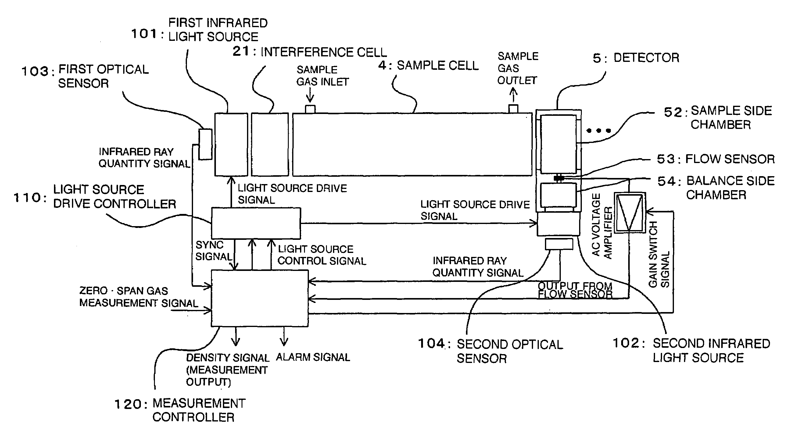
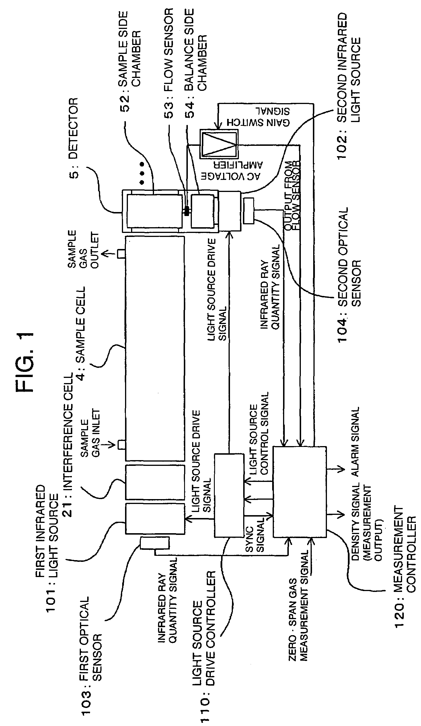
[0034]FIG. 1 is a block diagram showing one embodiment of an infrared gas analyzer, and an infrared gas analysis method using the same, according to the invention. In the figure, parts corresponding to those in FIG. 7 are denoted by like reference numerals. Reference numerals 101, 102 denote first and second infrared light sources, respectively, excellent in thermal responsiveness, such as one previously described with reference to FIG. 8, and the first infrared light source 101 irradiates a sample cell 4 with first infrared rays via an interference cell 21. Further, the second infrared light source 102 irradiates a balance side chamber 54 of a detector 5 with second infrared rays. In this case, the detector 5 has the balance side chamber 54 for receiving the second infrared rays, in place of the conventional reference side chamber 51, and a flow sensor 53 is provided in a gas distribution path linking a sample side chamber 52 for receiving the first infrared rays via the sample cel...
embodiment 2
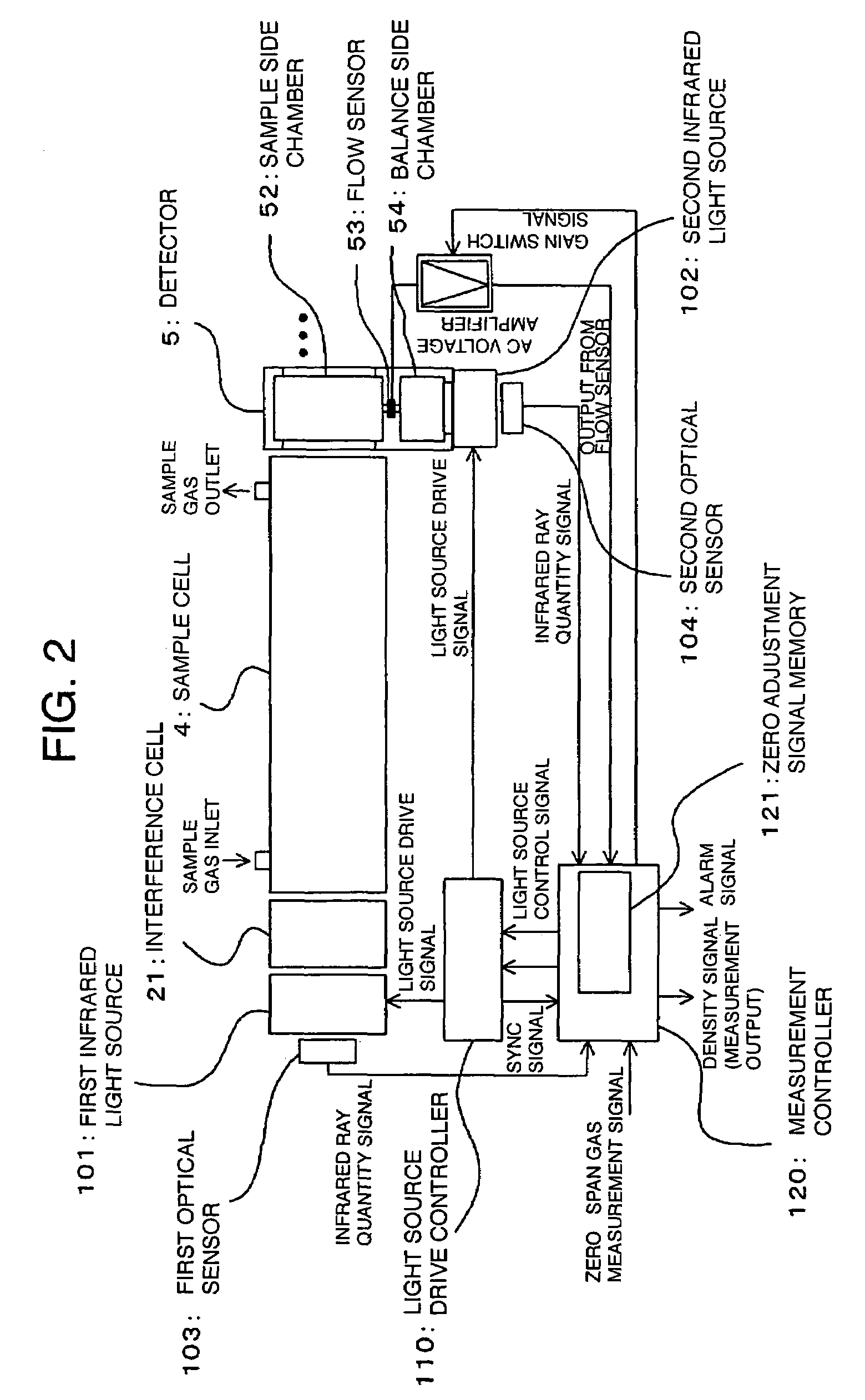
[0043]FIG. 2 is a block diagram showing another embodiment of an infrared gas analyzer, and an infrared gas analysis method using the same, according to the invention. In the figure, parts corresponding to those in FIG. 1 are denoted by like reference numerals. With the present embodiment shown in the figure, a drive amount of a second infrared light source 102 is adjusted at the time of a zero adjustment operation such that a difference between first infrared rays falling on a sample side chamber 52 of a detector5, via a sample cell 4, and second infrared rays falling directly on a balance side chamber 54 from the second infrared light source 102 becomes zero, and an output of the detector 5 (a flow sensor 53) becomes zero while the drive amount of the second infrared light source 102 is adjusted at the time of a measuring operation as well such that the output of the detector 5 (flow sensor 53) becomes zero, thereby obtaining a measurement output corresponding to concentration of ...
embodiment 3
[0046]FIG. 3 is a block diagram showing still another embodiment of an infrared gas analyzer, and an infrared gas analysis method using the same, according to the invention. In the figure, parts corresponding to those in FIG. 1 are denoted by like reference numerals. The present embodiment in the figure shows a specific configuration example of a light source drive controller 110 in FIG. 2 for driving first and second infrared light sources 101, 102, respectively. Reference numeral 113 denotes a synchronous controller for generating a sync signal rectangular in waveform, 111, 112 denote first and second light source drivers, respectively, for generating light source drive signals to be supplied to the first and second infrared light sources 101, 102, respectively, in response to the sync signal and light source control signals impressed from a measurement controller 120, and 105, 106 denote first and second drive signal detectors, respectively, for detecting the magnitudes of the re...
PUM
| Property | Measurement | Unit |
|---|---|---|
| concentration | aaaaa | aaaaa |
| concentrations | aaaaa | aaaaa |
| thermal responsiveness | aaaaa | aaaaa |
Abstract
Description
Claims
Application Information
 - R&D
- Intellectual Property
- Life Sciences
- Materials
- Tech Scout
- Unparalleled Data Quality
- Higher Quality Content
- 60% Fewer Hallucinations
Browse by: Latest US Patents, China's latest patents, Technical Efficacy Thesaurus, Application Domain, Technology Topic, Popular Technical Reports.
© 2025 PatSnap. All rights reserved.Legal|Privacy policy|Modern Slavery Act Transparency Statement|Sitemap|About US| Contact US: help@patsnap.com


