System and method for locating and communicating with personnel and equipment in a facility

a technology for facilities and personnel, applied in the field of facility control, management and communication systems, can solve the problems of increasing the cost of gps units, attenuating the reception of satellite signals, and increasing the redundancy of facilities, and achieve the effect of increasing redundancy

Inactive Publication Date: 2008-01-29
TIDEWATER HLDG
View PDF5 Cites 514 Cited by
  • Summary
  • Abstract
  • Description
  • Claims
  • Application Information

AI Technical Summary

Benefits of technology

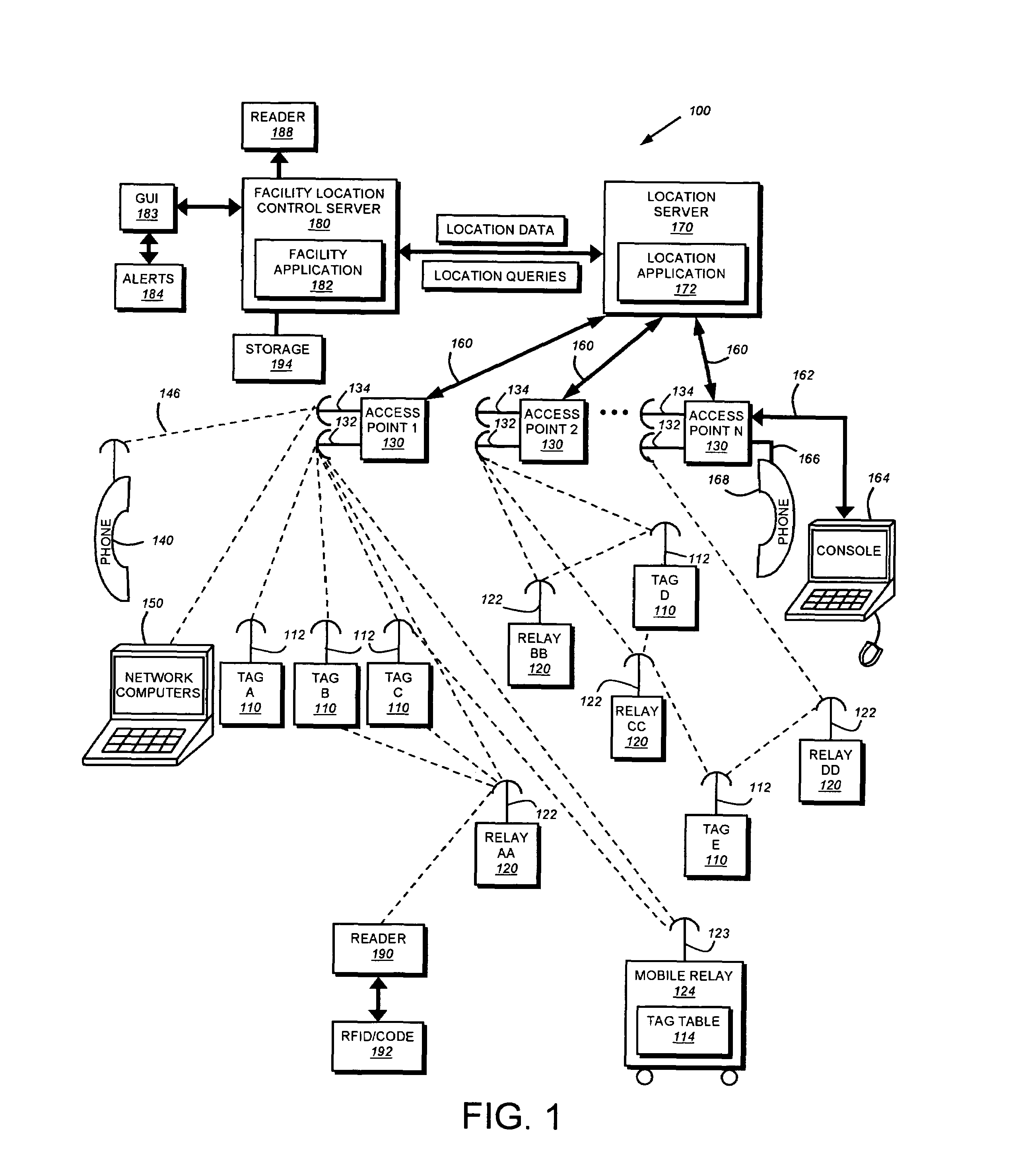
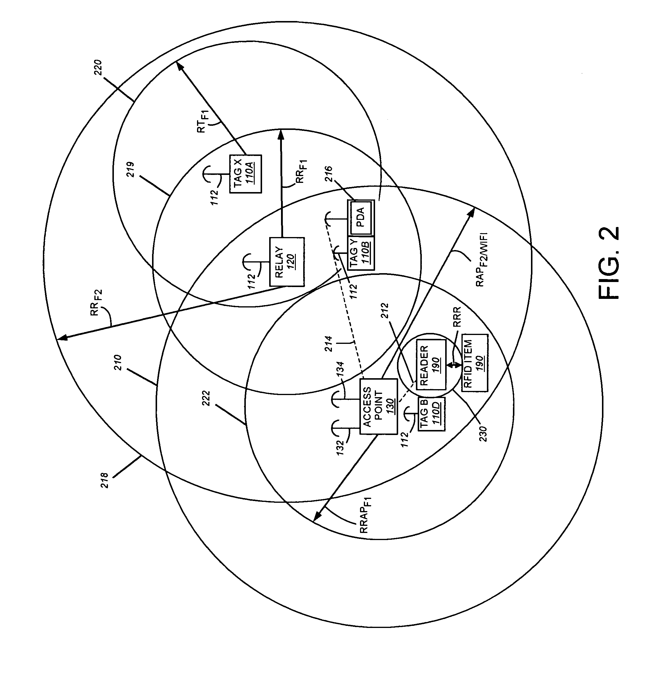
[0011]By employing a multiplicity of relays and relay functionalities (in access points and mobile units, for example), the system and method of this invention better ensures redundant identification of a given tag. That is, unlike triangulation systems with fewer, high-powered (costly) transceivers, a numerous array of more-closely spaced and simpler relays is deployed in the facility and a given tag is typically heard by a number of proximate relays (two or more in a given facility locus) at once. This provides the desired, increased redundancy in assuring the actual location of a given tag.

Problems solved by technology

This approach is problematic where reception of satellite signals is attenuated (e.g. indoors or in an area of heavy RF interference).
Likewise, this approach requires that expensive and complicated GPS units be attached to each subject for which location-determination is desired.
Again, this type of implementation is problematic where interference sources may move about the facility (for example diagnostic equipment in a hospital) or where a number of walls or fixed interference sources may serve to block one or more stations from full reception.
Typically, a triangulation-based system is plagued with RF “holes” or RF “distortions” that can only be filled with additional base station units.
These units may significantly add to the cost and obtrusiveness of such implementations.
Even where a location-determination system exhibits adequate coverage, it may lack many of the additional functions desired by facilities, such as hospitals.
However, this approach often carries the disadvantage of treating the facility's three-dimensional space as a single, large, undifferentiated area within which to locate items and persons.
This, in turn, dictates the use of complex installation and transmission / reception techniques for antenna alignment, particularly in a facility with many walls and / or interference sources.
Accuracy remains problematic for such systems due to the inevitable presence of significant RF reflections and wave attenuation as signals attempt to traverse disparate materials in the facility.

Method used


Image

  • System and method for locating and communicating with personnel and equipment in a facility
  • System and method for locating and communicating with personnel and equipment in a facility
  • System and method for locating and communicating with personnel and equipment in a facility

Examples


example 1

[0205]A warehouse has 30 employees and 50 types of equipment to perform its work. Not all employees have been trained and licensed to operate all the equipment. Employees each have assigned to them a PDA for the shift. A customer truck has arrived two hours ahead of schedule and needs to be loaded from the warehouse. While the warehouse has the authority to simply ask the truck driver to wait for his scheduled loading, with the system installed, it believes it can load the truck without delaying other customer schedules.

[0206]Instructions are sent over the WiFi LAN to PDA #8 to retrieve Pallet #73 (which is located by its asset tag location to be in Bay 56 of the warehouse). The system does not receive a response back from PDA #8, by WiFi LAN, confirming action taken to retrieve the pallet. A trigger event of non-response causes the system to look up which employee has been assigned PDA #8 for the day. It finds that employee K has been assigned the PDA. The employee is located, by h...

example 2

[0210]A large company with several thousand salespeople divides the U.S. into 50 regions, each with a small administrative support office. The regional support office is used mostly for training, but also has 15 cubicles for salespeople to employ when they find it productive to do so. The salespeople come and go at will, and are supported by two administrative secretaries, permanently assigned to the facility. As a salesperson arrives, their RF (Tag) badge is automatically recognized by the system and method of this invention, which is installed in the regional office and linked via office LAN, telephone and Internet communication to at least one location server and a management server / application. A salesperson can occupy any empty cubicle he or she wishes, and if none are available, a salesperson may use the meeting room space. The WiFi system will recognize their laptop IP address (already associated with them in the company records and management server), and permit LAN access, ...


PUM


Abstract

This invention provides a system and method for identifying, locating, authorizing by proximity and communicating with equipment and personnel in a facility that generally employs a series of limited range transceivers for location determination and a distributed wireless data network for data transfer. The system employs unique RF transceiver tags on personnel and equipment that are each uniquely identified and registered with a facility control application that oversees activities in the facility. The tags are tracked by RF communication based upon their proximity to one or more fixed-base networked access points and relays (which transfer location data by RF back to access points) within four range zones. Location data on all tags is uploaded periodically to a location server that interfaces with the facility control server. Tag data is monitored by the facility control server to track, authorize and deauthorize certain data transfers, movements and activities in accordance with rules established for each tag (or type of tag) within the facility control server's application. Wireless networking (WiFi, for example), in combination with the RF-derived location information, allows the facility control server to correlate and transmit data to staff in conjunction with location and proximity. WiFi can transmit authorizations, deauthorizations and general data based upon triggers established by proximity and location. Likewise, data can be transmitted over WiFi from readers etc. from personnel and equipment located and identified by the system.

Description

BACKGROUND OF THE INVENTION[0001]1. Field of the Invention[0002]This invention relates to facility control, management and communication systems.[0003]2. Background Information[0004]The use of radio frequency (RF) transceivers to establish the location of persons and things is becoming increasingly popular for use in facilities and other areas of interest. One popular approach involves the use of Global Positioning System (GPS) receivers appended to each person and item of interest. The receivers derive a global latitude and longitude position from a series of U.S. government satellites and, when needed, transmit this position to one or more base units with appropriate software to interpret the identity and location of the transmitter. The identity of the transmitter may be uniquely encoded with the position report so that a particular person or item can be correlated with a locational fix. This approach is problematic where reception of satellite signals is attenuated (e.g. indoors...

Claims


Application Information

Patent Timeline
Patent Type & Authority Patents(United States)
IPC IPC(8): G08B13/14G08B1/08G08B5/22
CPCG07C9/00111H04W4/80G07C9/28
Inventor ECKERT, DAVID D.BONTEMPS, EVAN J.CAREY, III, PAUL D.GOODWIN, RICHARD E.HATFIELD, KEITH E.LORENZ, JOSEPH P.NEVISH, KEITH A.SPANG, EDWARD J.WESTERBERG, GLEN S.
Owner TIDEWATER HLDG
Why Eureka
Try Eureka