Coolant penetrating cold-end pressure vessel

a technology of cold-end pressure vessel and cooling structure, which is applied in the direction of machines/engines, mechanical equipment, lighting and heating apparatus, etc., can solve the problem of limiting the maximum allowed working pressure and therefore the power of the engin

Inactive Publication Date: 2008-02-05
NEW POWER CONCEPTS
View PDF31 Cites 51 Cited by
  • Summary
  • Abstract
  • Description
  • Claims
  • Application Information

AI Technical Summary

Problems solved by technology

The two functions of heat transfer and pressure containment produce competing demands on the design.
However, thin walls of weak materials limit the maximum allowed working pressure and therefore the power of the engine.

Method used


Image

  • Coolant penetrating cold-end pressure vessel
  • Coolant penetrating cold-end pressure vessel
  • Coolant penetrating cold-end pressure vessel

Examples


Embodiment Construction

[0021]In accordance with embodiments of the present invention, the heat transfer and pressure vessel functions of the cooler of a pressurized close-cycle machine are separated, thereby advantageously maximizing both the cooling of the working gas and the allowed working pressure of the working gas. Increasing the maximum allowed working pressure and cooling both result in increased engine power. Embodiments of the invention achieve good heat transfer and meet code requirements for pressure containment by using small (relative to the heater head diameter) metal tubing to transfer heat and separate the cooling fluid from the high pressure working gas.

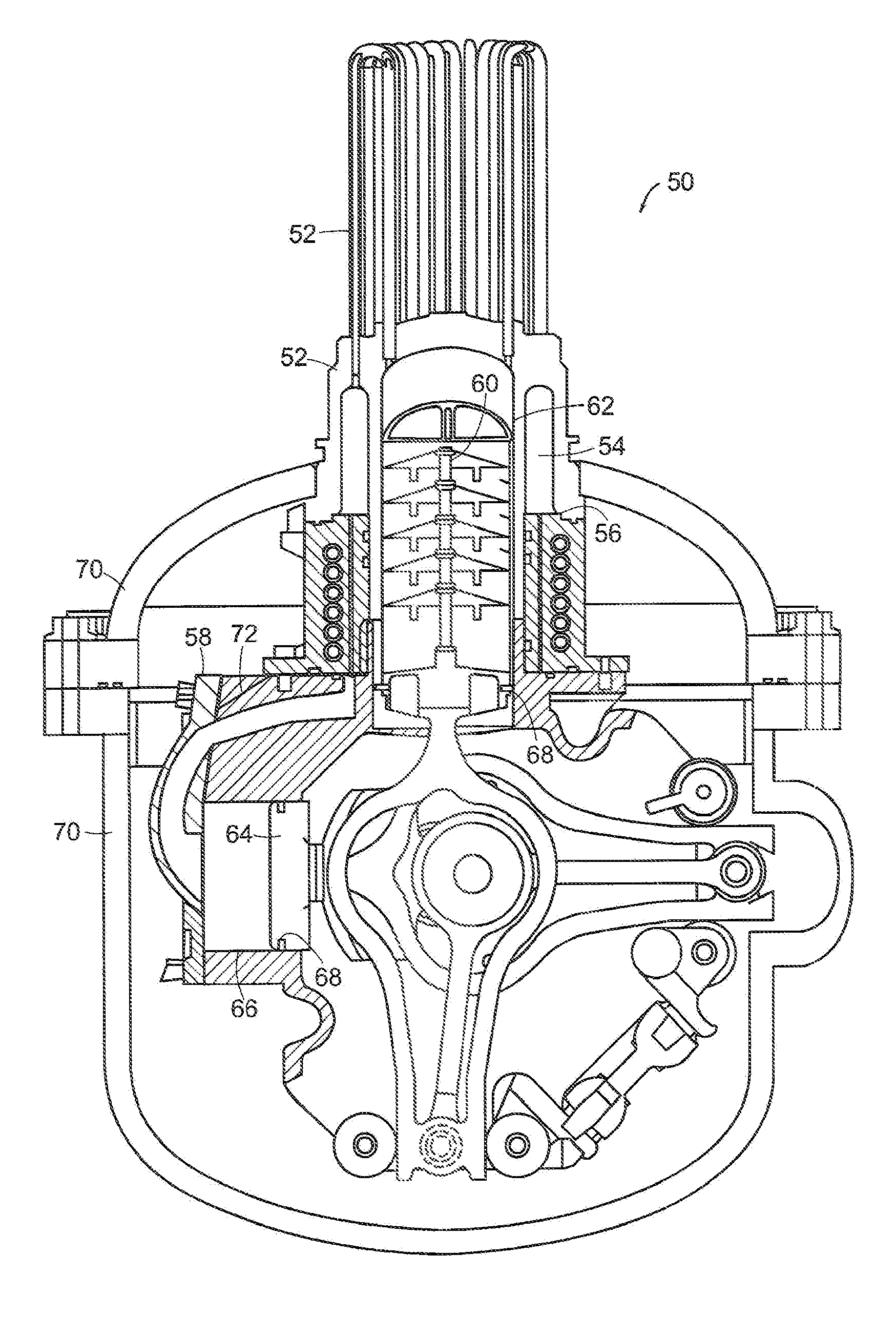
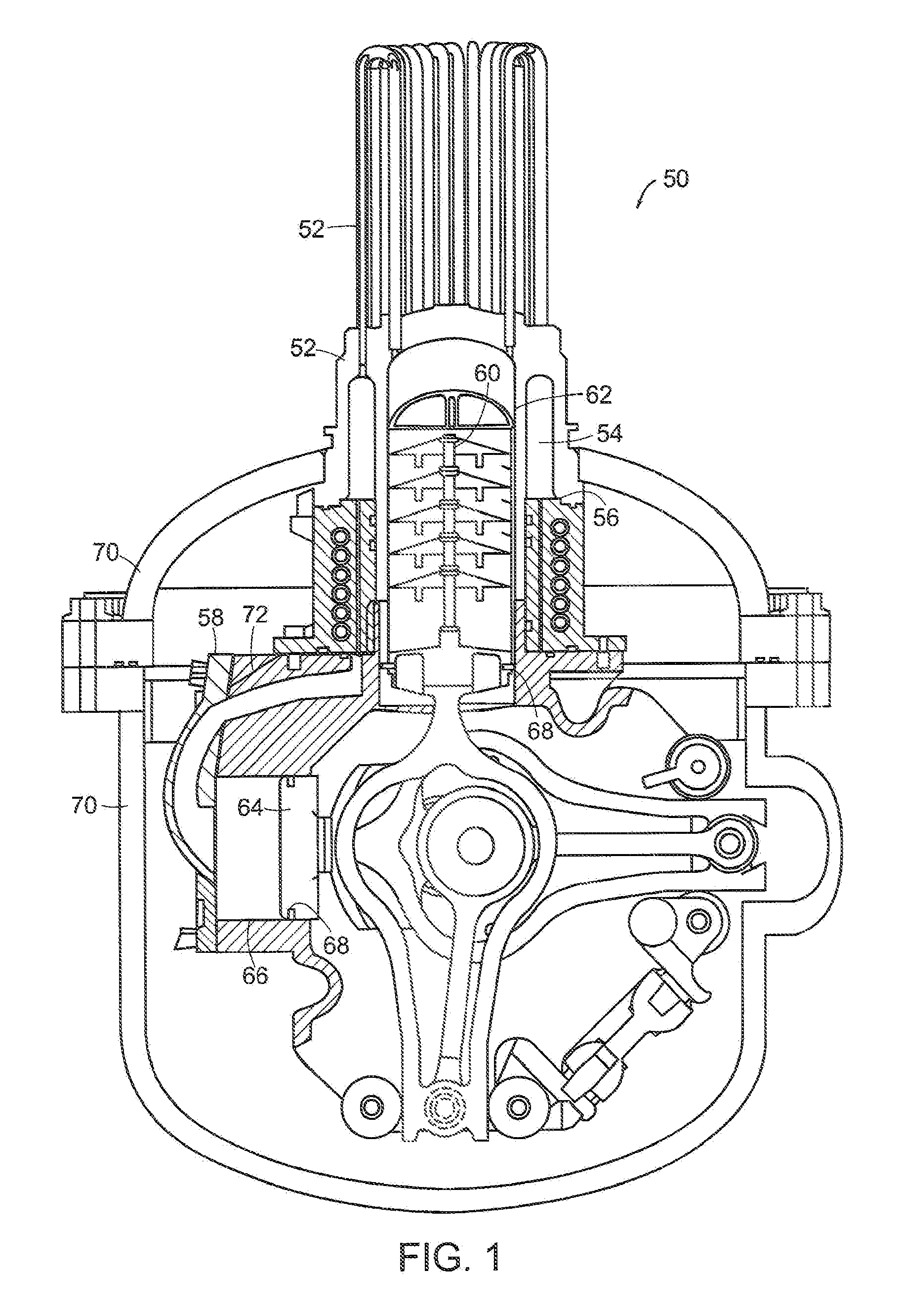
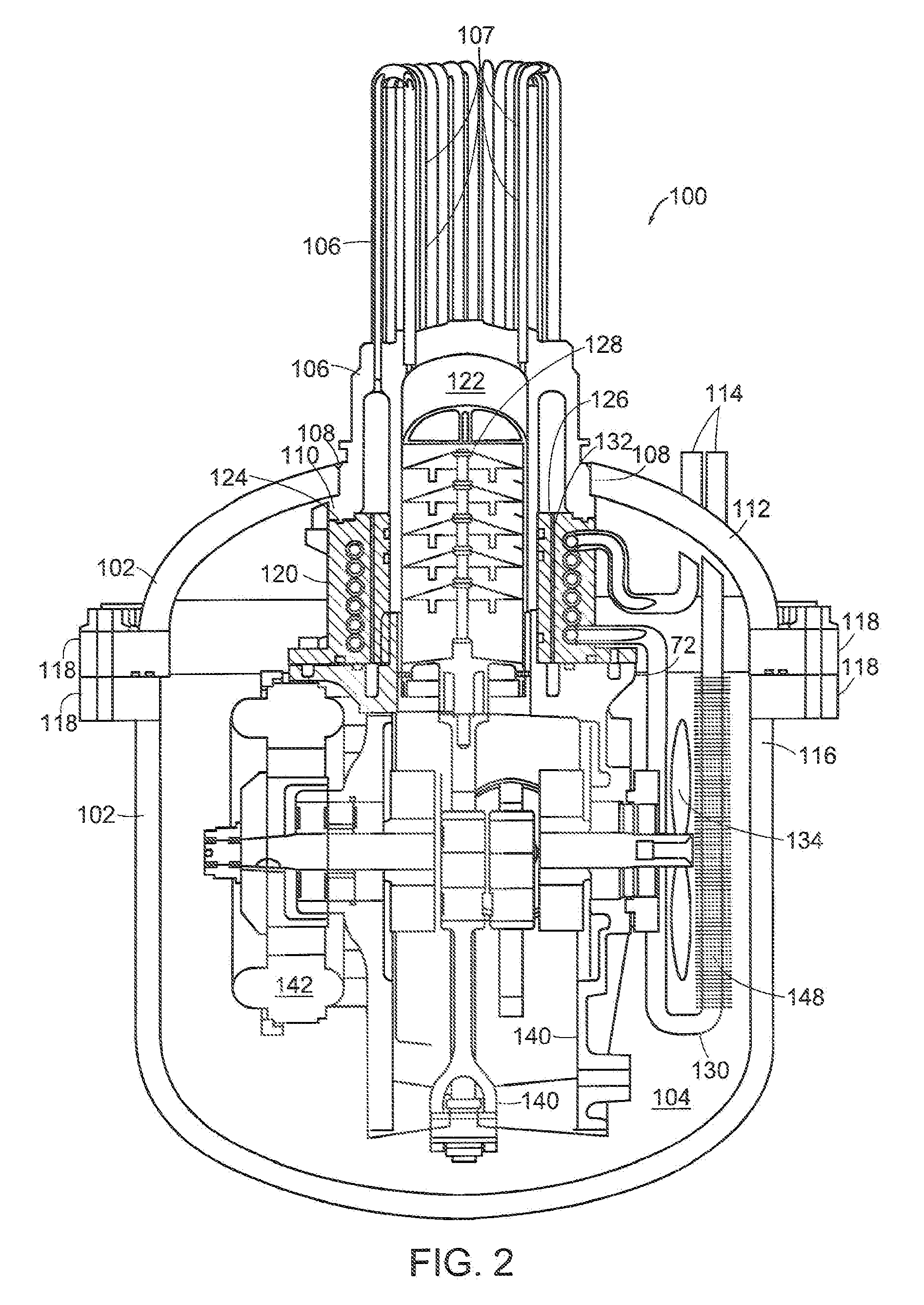
[0022]Referring now to FIG. 1, a hermetically sealed Stirling cycle engine, in accordance with preferred embodiments of the present invention, is shown in cross section and designated generally by numeral 50. While the invention will be described generally with reference to a Stirling engine as shown in FIG. 1 and FIG. 2, it is to be unde...


PUM

PropertyMeasurementUnit
pressureaaaaaaaaaa
diameteraaaaaaaaaa
pressureaaaaaaaaaa

Abstract

An improvement is provided to a pressurized close-cycle machine that has a cold-end pressure vessel and is of the type having a piston undergoing reciprocating linear motion within a cylinder containing a working fluid heated by conduction through a heater head by heat from an external thermal source. The improvement includes a heat exchanger for cooling the working fluid, where the heat exchanger is disposed within the cold-end pressure vessel. The heater head may be directly coupled to the cold-end pressure vessel by welding or other methods. A coolant tube is used to convey coolant through the heat exchanger.

Description

TECHNICAL FIELD[0001]The present invention pertains to the pressure containment structure and cooling of a pressurized close-cycle machine.BACKGROUND OF THE INVENTION[0002]Stirling cycle machines, including engines and refrigerators, have a long technological heritage, described in detail in Walker, Stirling Engines, Oxford University Press (1980), incorporated herein by reference. The principle underlying the Stirling cycle engine is the mechanical realization of the Stirling thermodynamic cycle: isovolumetric heating of a gas within a cylinder, isothermal expansion of the gas (during which work is performed by driving a piston), isovolumetric cooling, and isothermal compression.[0003]In the prior art, the heat transfer structure between the working gas and the cooling fluid also contains the high pressure working gas of the Stirling cycle engine. The two functions of heat transfer and pressure containment produce competing demands on the design. Heat transfer is maximized by as th...

Claims


Application Information

Patent Timeline
Patent Type & Authority Patents(United States)
IPC IPC(8): F01B29/10F02G1/055
CPCF02G1/055F02G2243/04Y10T29/49391F02G2256/04F02G2256/00F02G1/057F02G2256/02F02G2256/50F28F1/42
Inventor STRIMLING, JONATHANBOUCHARD, CLEMENT D.GURSKI, THOMAS Q.LANGENFELD, CHRISTOPHER C.NORRIS, MICHAELLAROCQUE, RYAN KEITH
Owner NEW POWER CONCEPTS
Why Eureka
Try Eureka