Method, computer program, and control and/or regulating unit for operating an internal combustion engine

a technology for internal combustion engines and fuel pumps, which is applied in the direction of fuel injecting pumps, electric control, machines/engines, etc., can solve the problems of major pressure pulsation in the low-pressure fuel line, affecting the partial load efficiency of these high-pressure fuel pumps, and reducing the heating of fuel. , the effect of improving the partial load efficiency of the high-pressure fuel pump

Inactive Publication Date: 2008-02-05
ROBERT BOSCH GMBH
View PDF10 Cites 11 Cited by
  • Summary
  • Abstract
  • Description
  • Claims
  • Application Information

AI Technical Summary

Benefits of technology

[0007]In the method of the invention, only as much fuel as is to be pumped into the high-pressure fuel line in the ensuing pumping stroke reaches the pumping chamber of the high-pressure fuel pump. Pumping fuel back and forth from the low-pressure fuel line into the pumping chamber and back again is thus avoided. As a consequence, the partial-load efficiency of the high-pressure fuel pump is markedly improved and heating of the fuel is reduced to the same extent.
[0008]Since high-pressure fuel pumps in injection systems are operated in the partial-load operating mode during virtually the entire time in operation, the improvement in the partial-load efficiency of the high-pressure fuel pump of the invention has a major effect on the overall utilization rate of the fuel injection system. Moreover, with the aid of the method of the invention, an intake valve between the low-pressure fuel line and the pumping chamber can be dispensed with.
[0009]When the intake phase begins at top dead center of the piston, the triggering of the quantity control valve is especially simple, above all at very small pumping quantities, since because of the sinusoidal course of the speed of the piston, the piston speed in the vicinity of top dead center is relatively slight, and hence the demands in terms of the precision of the triggering of the quantity control valve are relatively slight as well.
[0016]To simplify the triggering of the quantity control valve and to relieve the associated control and / or regulating unit of the high-pressure fuel pump, it may be provided in a further advantageous feature that a check valve is provided between the quantity control valve and the pumping chamber. In advantageous embodiments of the invention, the quantity control valve and the check valve are combined into a structural unit, so that the assembly and testing of this unit can be done outside the high-pressure fuel pump.

Problems solved by technology

This aspiration of fuel from the low-pressure fuel line into the pumping chamber and the ensuing at least partial pushing back of this fuel into the low-pressure fuel line impairs the partial-load efficiency of these high-pressure fuel pumps and leads to unwanted warming of the fuel.
The diversion of the excess fuel quantity from the pumping chamber furthermore causes major pressure pulsations in the low-pressure fuel line.
This increases the costs for a fuel injection system considerably.

Method used


Image

  • Method, computer program, and control and/or regulating unit for operating an internal combustion engine
  • Method, computer program, and control and/or regulating unit for operating an internal combustion engine
  • Method, computer program, and control and/or regulating unit for operating an internal combustion engine

Examples


Embodiment Construction

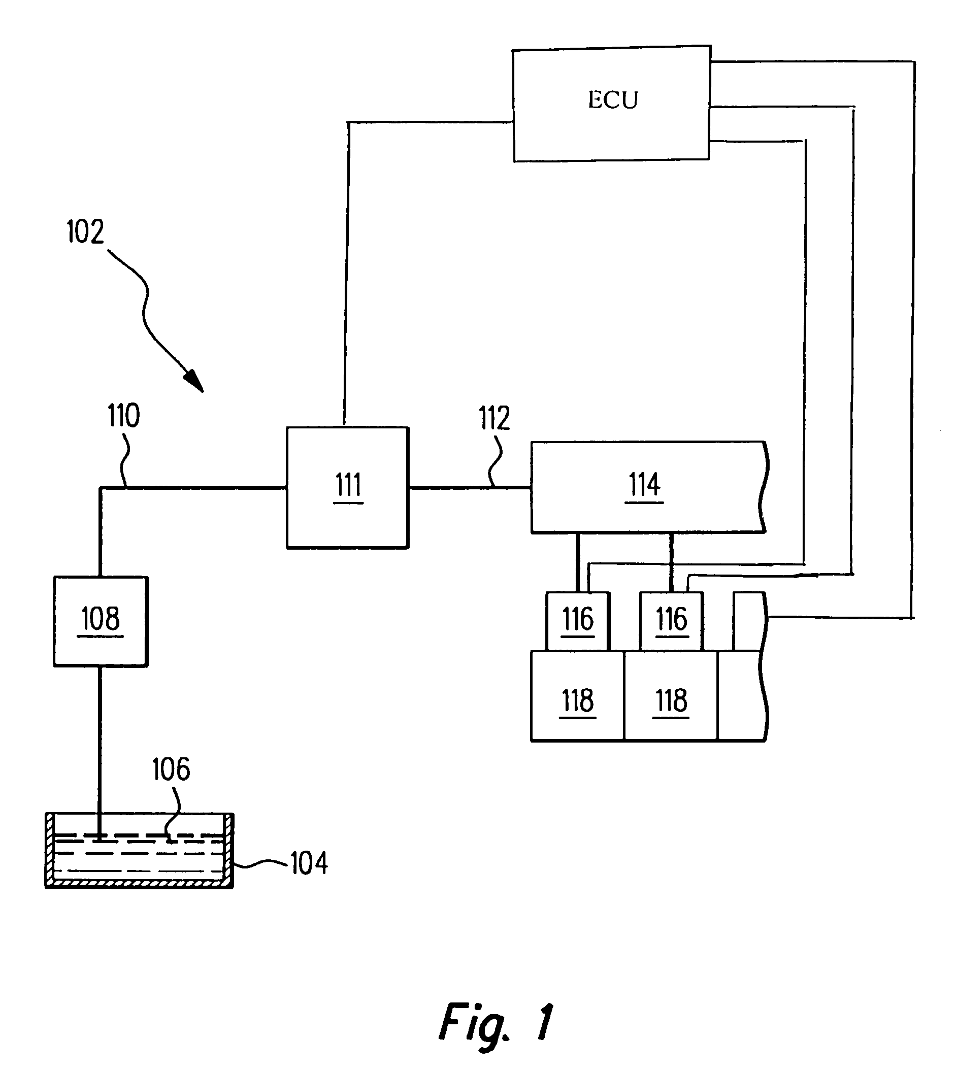
[0025]The construction of a fuel injection system 102 will be explained below in conjunction with the block circuit diagram shown in FIG. 1. The fuel injection system 102 includes a fuel tank 104, from which fuel 106 is pumped by an electric or mechanical prefeed pump 108. Via a low-pressure fuel line 110, the fuel 106 is pumped to a high-pressure fuel pump 111. From the high-pressure fuel pump 111, via a high-pressure fuel line 112, the fuel 106 reaches a common rail 114. A plurality of fuel injection nozzles or injectors 116 are connected to the common rail and inject the fuel 106 directly into combustion chambers 118 of an internal combustion engine, not shown.

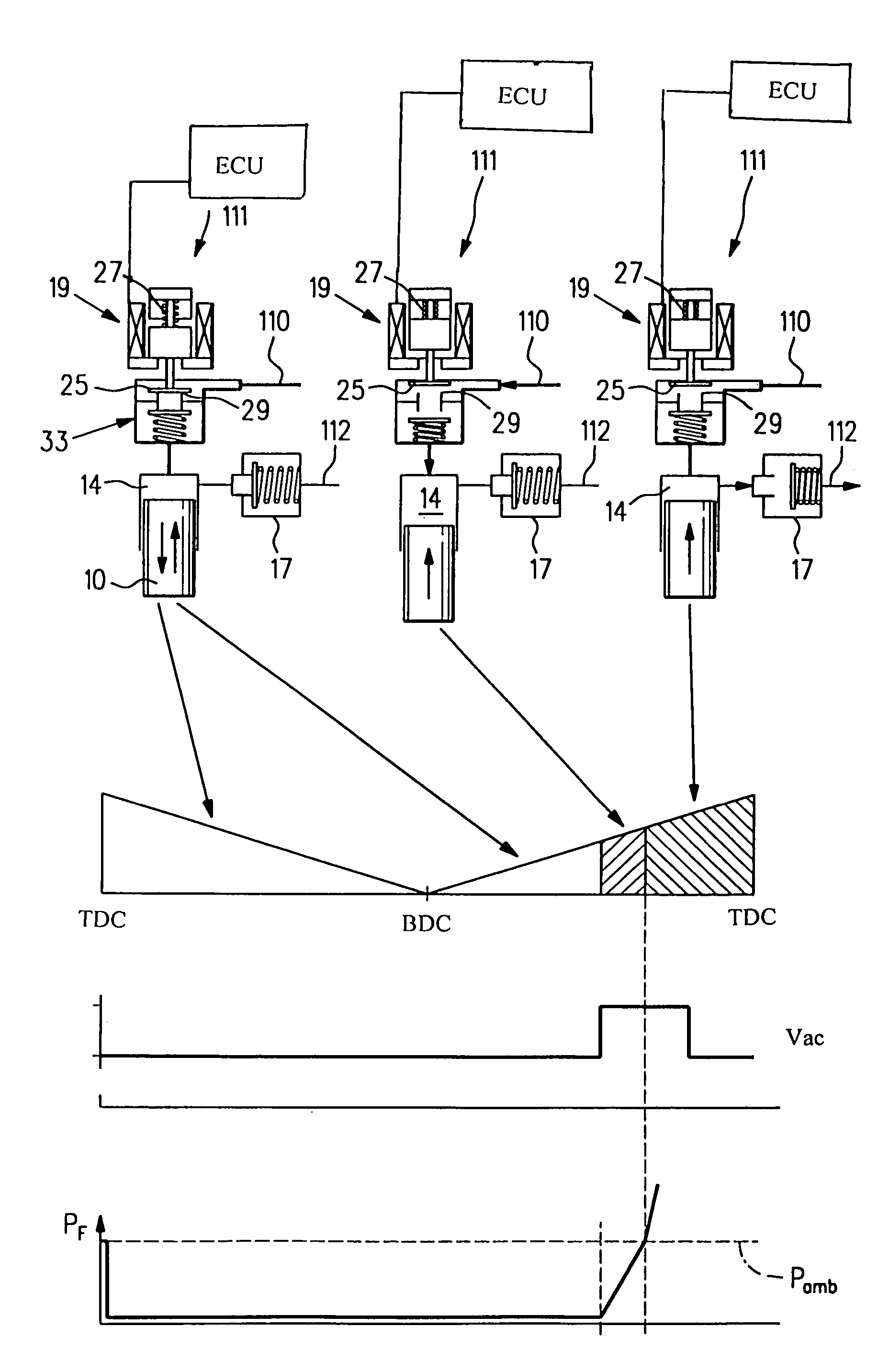
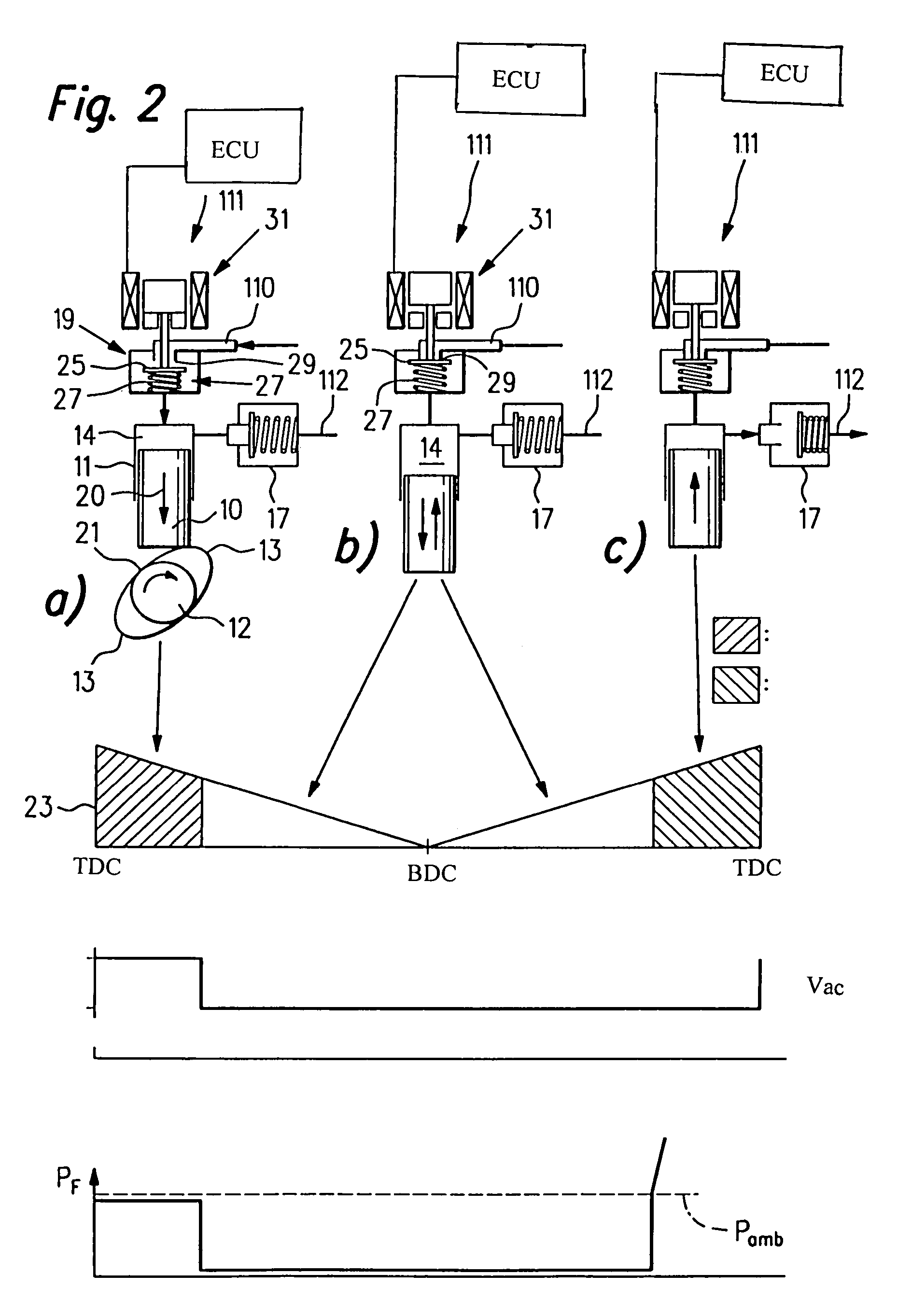
[0026]In FIG. 2a, a high-pressure fuel pump 111 is shown schematically. The high-pressure fuel pump 111 includes a piston 10, which is guided in a cylinder 11 and is driven by a camshaft 12 with two cams 13. The piston 10 and the cylinder 11 define a pumping chamber 14. The low-pressure fuel line 110 and a high-pressure fue...


PUM


Abstract

A high-pressure fuel pump and methods for controlling this high-pressure fuel pump are described in which the pumping quantity regulation does not cause significant heating of the fuel to be pumped. The partial-load efficiency of the high-pressure fuel pump, triggered in accordance with the invention, is also very good.

Description

CROSS-REFERENCE TO RELATED APPLICATIONS[0001]This application is based on German Patent Application 10 2004 056 665.8 filed Nov. 24, 2004, upon which priority is claimed.BACKGROUND OF THE INVENTION[0002]1. Field of the Invention[0003]The invention is directed to an improved high-pressure fuel pump for an internal combustion engine, the pump having a piston oscillating in a cylinder, in which the cylinder and the piston define a pumping chamber, and the pumping chamber communicates on the intake side with a low-pressure fuel line and on the compression side with a high-pressure fuel line, and having a quantity control valve located between the low-pressure line and the pumping chamber.[0004]2. Description of the Prior Art[0005]High-pressure fuel pumps of the type with which this invention is concerned are known, for instance from German Patent Disclosure DE 198 34 120 A1, DE 100 52 629 A1, or DE 102 00 987 A1. In all these high-pressure fuel pumps, the pumping quantity of the high-pr...

Claims


Application Information

Patent Timeline
Patent Type & Authority Patents(United States)
IPC IPC(8): F02M37/04
CPCF02D41/406F02M59/02F02M59/24F02M59/366F02M59/367F02M59/102F02M63/0225F02M2200/21Y02T10/44Y02T10/40
Inventor MUELLER, UWESCHROEDER, BERNDHOLLMANN, TIMM
Owner ROBERT BOSCH GMBH
Why Eureka
Try Eureka