Floor covering removal and impact tool

a technology of impact tool and floor covering, which is applied in the direction of manufacturing tools, portable drilling machines, building repairs, etc., can solve the problems of laborious and exhaustive tasks of carpet removal

Active Publication Date: 2008-02-05
FATHOM LEAKS
View PDF13 Cites 13 Cited by
  • Summary
  • Abstract
  • Description
  • Claims
  • Application Information

AI Technical Summary

Benefits of technology

[0010]The handle and the anvil are movable relative to the collar, the guide rods, the sheath and the blade unit. The sheath prevents entry of foreign material and engagement of one's hands between the collar and the blade unit. The anvil and the collar are both cylindrically shaped. The collar and the blade unit are attached to the guide rods by fasteners. The anvil is attached to the rod by fasteners also. The sheath is held fixed on the blade unit by means of a retaining bolt passing through aligned throughholes formed in the upper portion of the blade unit and the sheath. A locking device passes through the sheath and the rod for preventing sliding movement of the rod and the anvil.
[0011]In another aspect of the invention, there is provided an impact and floor covering removable tool including an elongated movable rod having an upper end and a lower end. A handle is connected generally transversely to the upper end of the rod. An anvil is fixed to the lower end of the rod and has a pair of spaced openings formed therethrough. A collar is mounted above the anvil for selective engagement therewith, the rod passing through the collar. A replaceable blade unit is disposed below the anvil and has an upper fluted portion disposed for selective engagement with the anvil, and a lower blade edge portion adapted to be wedged between a floor surface and a floor covering. A guide rod structure extends between the collar and the upper fluted portion and passes through the openings in the anvil on opposite sides of the rod. The guide structure enables sliding movement of the anvil between the collar and the blade unit. A sheath surrounds the collar, the anvil and portions of the rod and the blade unit. The sheath is removably connected to the upper portion of the blade unit. A locking arrangement selectively connects the sheath and the rod to prevent sliding movement of the rod and anvil relative to the collar, blade unit, guide rod structure and sheath.

Problems solved by technology

Applicant had discovered it is a laborious and exhaustive task to remove carpeting as well as ceramic and vinyl tiles from floor surfaces.

Method used


Image

  • Floor covering removal and impact tool
  • Floor covering removal and impact tool
  • Floor covering removal and impact tool

Examples


Embodiment Construction

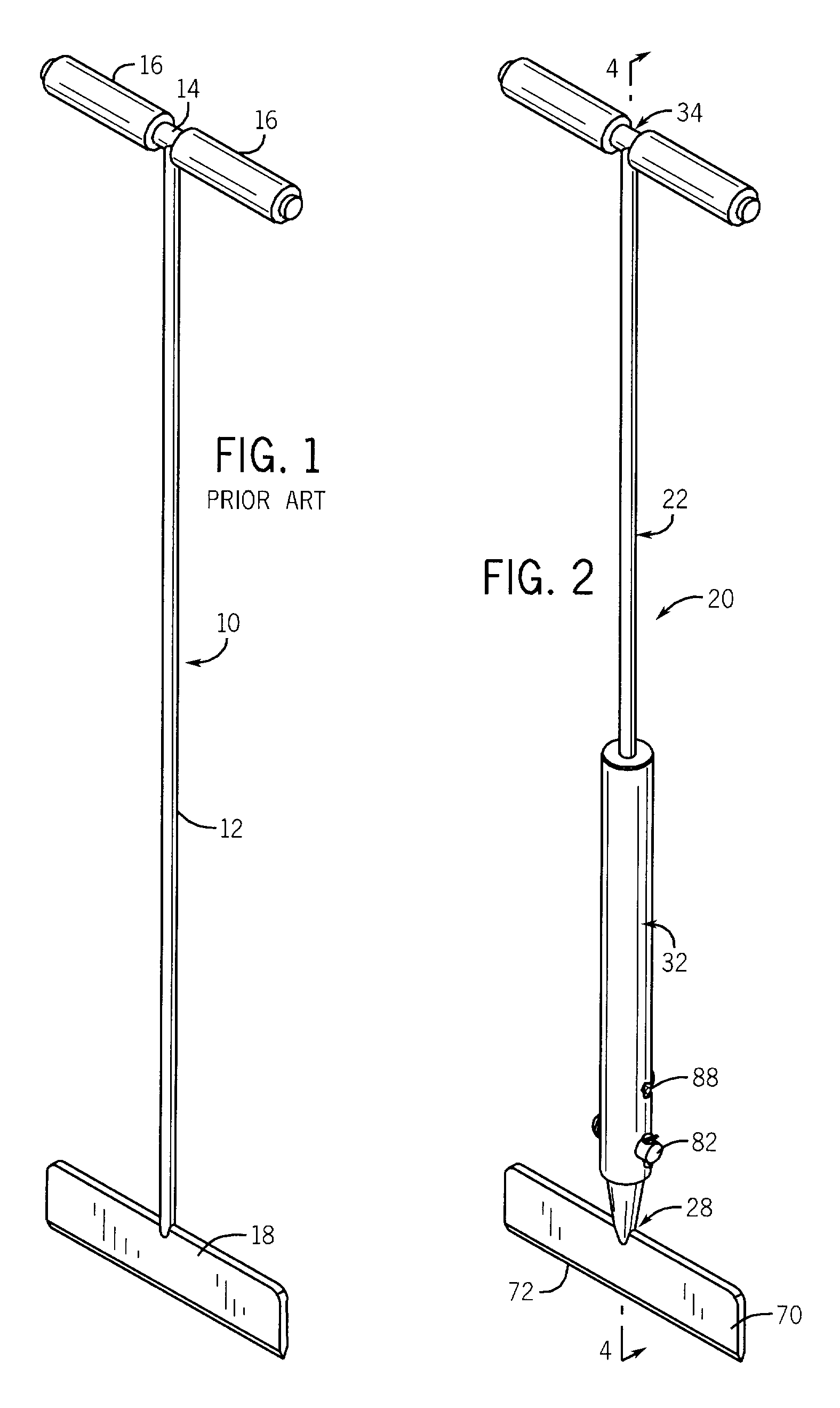
[0023]Referring now to FIG. 1, thereshown is a prior art floor covering removal tool 10 which is comprised of an elongated solid rod 12 and a solid handle 14 fixed such as by welding to the top of the rod 12. The opposite ends of the handles 14 are typically equipped with rubber handgrips 16 to protect one's hands during use. The bottom of the rod 12 is provided with a blade 18 for engaging a floor covering element intended for removal. The rod 12, handle 14, and blade 18 are fabricated from a rigid metal such as steel which will withstand the forces applied to the rod 12 as the tool 10 is moved in a shoveling motion to drive the blade 18 between carpet or tile and a floor surface to which the carpet or tile is attached.

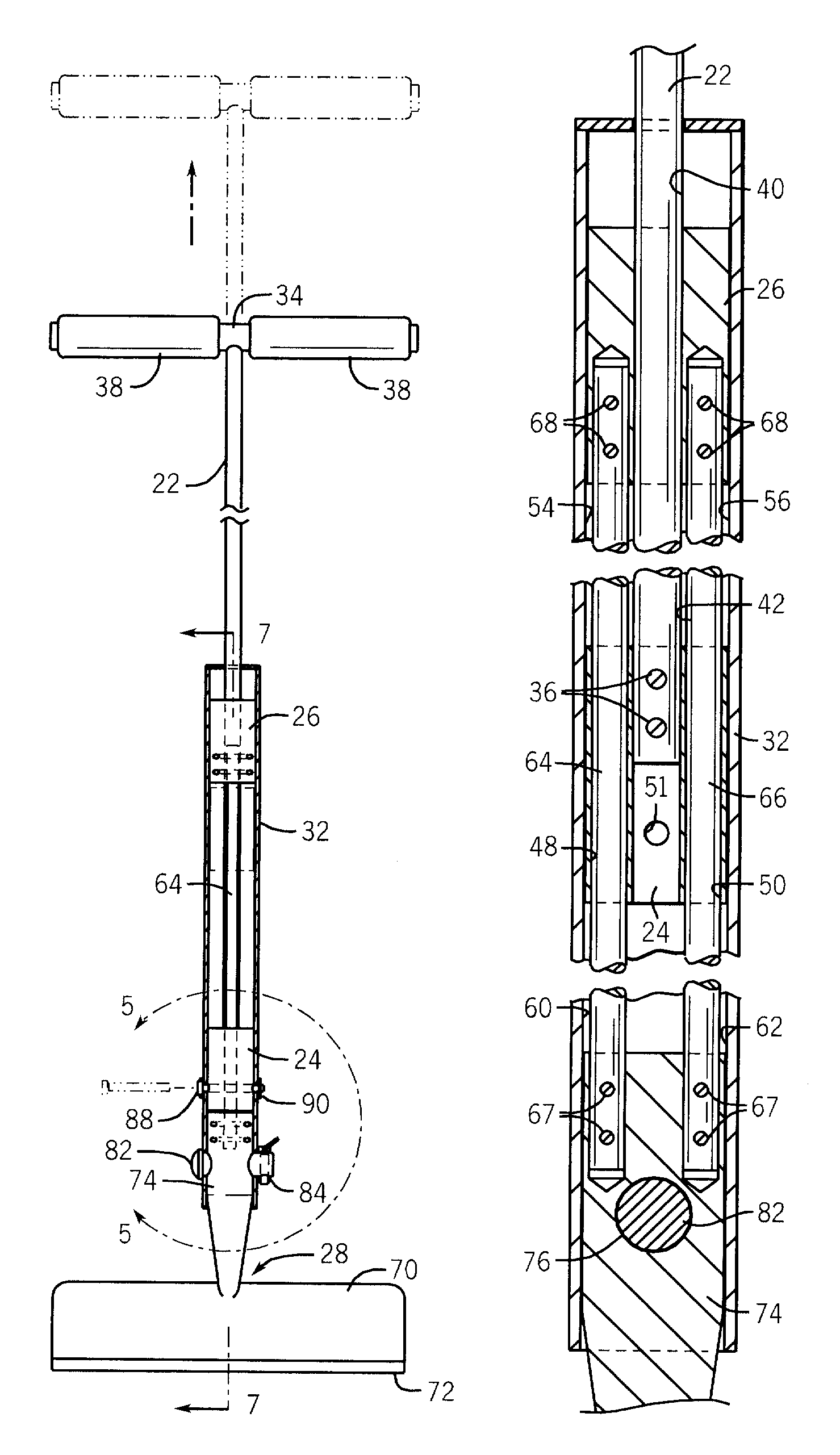
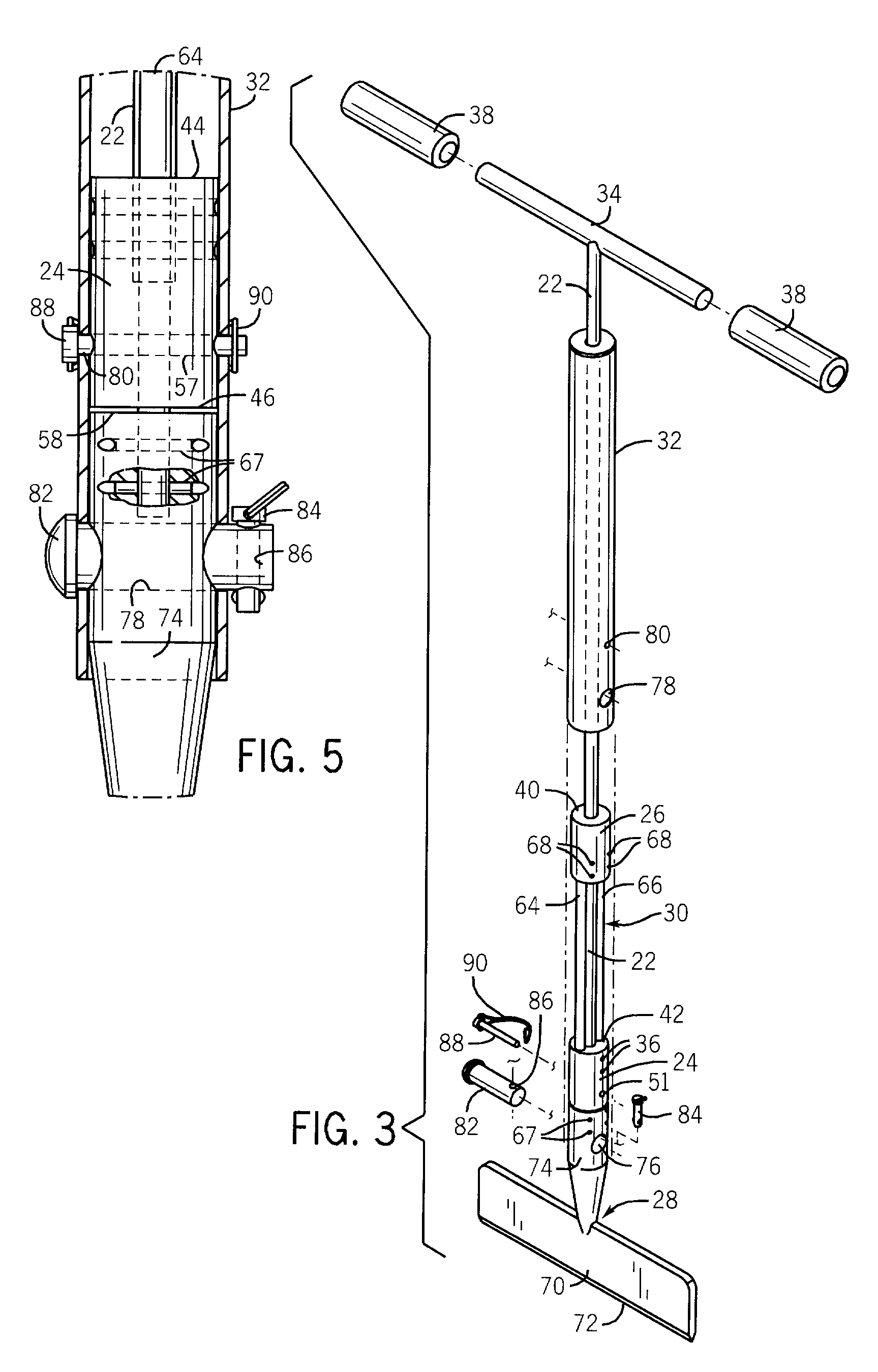
[0024]FIGS. 2-6 illustrate a floor covering removal and impact tool 20 embodying the present invention. The impact tool 20 is comprised of an elongated movable solid rod 22, a movable solid cylindrical anvil 24, a cylindrical collar 26, a replaceable blade unit 28, a...


PUM

PropertyMeasurementUnit
sliding movementaaaaaaaaaa
forcesaaaaaaaaaa
contact surfaceaaaaaaaaaa

Abstract

An impact tool particularly useful for floor removal material includes an elongated removable rod having an upper end and a lower end. A handle is connected to the upper end of the rod, and an anvil is fixed to the lower end of the rod. A collar is mounted above the anvil with the rod passing therethrough. A replacement blade unit is disposed below the anvil and has an upper portion and a lower portion having a separating blade edge. A pair of guide rods extends between the collar and the upper portion of the blade unit and passes through the anvil on opposite sides of the rod. The guide rods enable sliding movement of the anvil therealong between the collar and the blade unit as the handle and rod are moved up and down. A tubular sheath is telescoped over a portion of the rod, the collar, the anvil and the upper portion of the blade unit, and is connected to the upper portion of the blade unit.

Description

FIELD OF THE INVENTION[0001]The present invention relates generally to a manually-operated impact tool and, more particularly, pertains to an impact tool for enabling the removal of floor covering such as carpet and tile.BACKGROUND OF THE INVENTION[0002]Applicant is the inventor of a feeler rod for water mains as disclosed in U.S. Pat. No. 6,148,929 issued Nov. 21, 2000. In this patent, a leak detection device is provided to locate fluid leaks in a ground surface and includes an elongated rod having a handle transversely attached thereto. The device includes an anvil fixed to the rod and having a pair of spaced openings formed therethrough. A first collar is slidably mounted on the rod in spaced relationship above the anvil for selective engagement therewith. A second collar is slidably mounted on the rod in spaced relationship below the anvil for selective engagement therewith. A guide rod structure extends between the first and second collars and passes through openings formed in ...

Claims


Application Information

Patent Timeline
Patent Type & Authority Patents(United States)
IPC IPC(8): B25C1/02
CPCB29C63/0013E04G23/006
Inventor WINTERS, LARRY
Owner FATHOM LEAKS
Why Eureka
Try Eureka