Light-emitting diode (LED) illumination system for a digital micro-mirror device (DMD) and method of providing same

a technology of digital micro-mirror devices and illumination systems, which is applied in lighting and heating apparatus, non-linear optics, instruments, etc., can solve the problems of unfiltered uv light reducing the lifetime of both optical components and micro-display panels within the system, and the limited number of manufacturers is capable of producing high-quality short-arc lamps

Active Publication Date: 2008-02-05
JABIL CIRCUIT INC
View PDF14 Cites 90 Cited by
  • Summary
  • Abstract
  • Description
  • Claims
  • Application Information

AI Technical Summary

Problems solved by technology

Two drawbacks to using the fly's-eye type of optical system are that it is bulky and expensive to manufacture.
Currently, only a limited number of manufacturers are capable of producing high-quality short arc lamps.
The unfiltered UV light reduces the lifetime of both the optical components and microdisplay panel within the system, while IR light requires additional cooling devices to maintain a desired operating temperature.
A problem exists in this type of system in view of the coupling between LEDs and fibers.
In practice, due to coupling and transmission loss, it is difficult to efficiently couple light emitting from the LED arrays to the corresponding fiber bundles and waveguides.
Generally, a common problem within these prior art systems is that some light from LEDs cannot enter the corresponding lens of the first and second fly's-eye lenses due to aberration and aperture limitation of the lens array.
Therefore, a portion of the illumination light will fall outside of the panel area, resulting in low light efficiency and low contrast.

Method used


Image

  • Light-emitting diode (LED) illumination system for a digital micro-mirror device (DMD) and method of providing same
  • Light-emitting diode (LED) illumination system for a digital micro-mirror device (DMD) and method of providing same
  • Light-emitting diode (LED) illumination system for a digital micro-mirror device (DMD) and method of providing same

Examples


Embodiment Construction

[0028]The present description is directed in particular to elements forming part of, or cooperating more directly with, the apparatus in accordance with the invention.

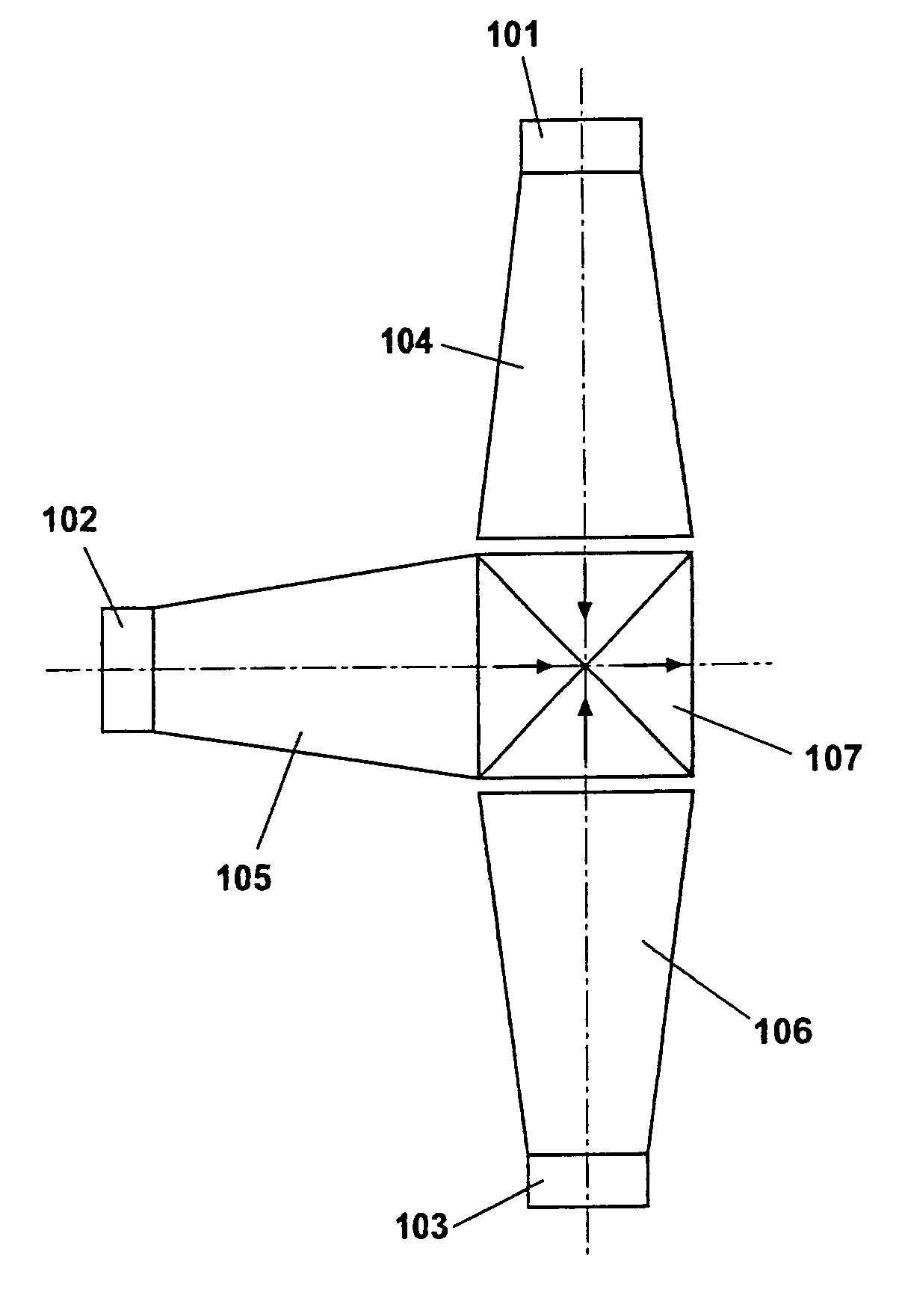
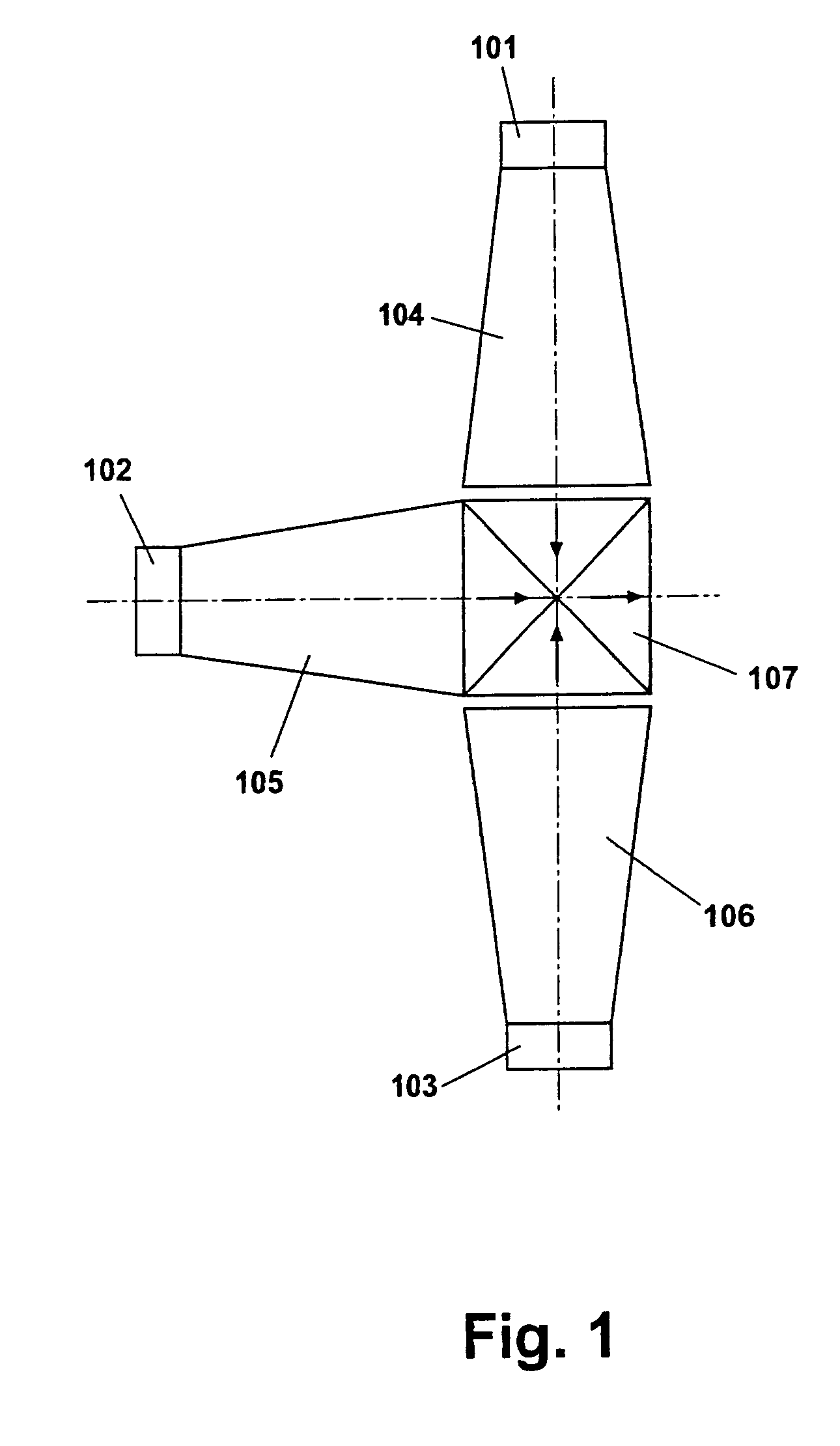
[0029]Turning now to the figures, FIG. 1 is a block diagram depicting a polarized light illumination assembly in accordance with the present invention which includes a red LED 101, a green LED 102, a blue LED 103, three tapered waveguides 104, 105, 106, and a cross-dichroic combiner 107. The light beams emitting from the red LED 101, green LED 102 and blue LED 103 are homogenized and guided by tapered waveguides 104, 105 and 106, respectively. The light exit faces of the waveguides are connected to three entrance surfaces of the non-polarized cross-dichroic combiner 107. The green light transmits through the dichroic combiner 107 while the red and blue light beams are reflected from the dichroic combiner 107. As will be evident to those skilled in the art, the tapered waveguides 104, 105 and 106 are structures that “gu...


PUM


Abstract

A light illumination system for projecting a color image to a digital micro-mirror display (DMD) panel includes a light-emitting diode (LED) illumination assembly (101, 102, 103), a dichroic combiner (107) for providing a single light source and a condenser lens system (FIGS. 20-23) for directing light from the single light source to the DMD panel. The invention provides a cost effective and efficient system for providing a non-polarized uniform light source to a DMD panel.

Description

CROSS-REFERENCE TO RELATED APPLICATIONS[0001]Priority for this non-provisional application is based on provisional patent application entitled LED Polarizing Optics for Color Illumination System, Ser. No. 60 / 646,775, filed Jan. 25, 2005; LED Color Illumination Apparatus for Polarized Light Projection System, Ser. No. 60 / 646,777, filed Jan. 25, 2005; and RGB LED Illumination Apparatus for DLP Projection Applications, Ser. No. 60 / 646,778, filed Jan. 25, 2005, all owned by Jabil Circuit, Inc.FIELD OF THE INVENTION[0002]This invention generally relates to a polarized light illumination apparatus to provide illumination for a microdisplay projection-type display system.BACKGROUND OF THE INVENTION[0003]In recent years, digital projection systems using spatial light valve modulators, such as a digital micromirror device (hereafter “DMD”), transmissive liquid crystal display (hereafter “LCD”) and reflective liquid crystal on silicon (hereafter “LCoS”) have been receiving much attention as t...

Claims


Application Information

Patent Timeline
Patent Type & Authority Patents(United States)
IPC IPC(8): F21V7/04
CPCG02B27/1006G02B27/1033G02B27/145G02B27/149H04N9/3152H04N9/3164H04N9/3197G03B21/2073G03B21/2033G03B21/208Y10S362/80
Inventor MOREJON, ISRAEL J.ZHAI, JINHUILI, HAIZHANG
Owner JABIL CIRCUIT INC
Why Eureka
Try Eureka