Rotary pulser for transmitting information to the surface from a drill string down hole in a well

a technology of rotary pulser and drill string, which is applied in the direction of instruments, borehole/well accessories, surveys, etc., can solve the problems of vibration wear and abrasion of the drill string, and large pressure on the components of the drill string

Active Publication Date: 2008-02-05
APS TECH
View PDF59 Cites 93 Cited by
  • Summary
  • Abstract
  • Description
  • Claims
  • Application Information

AI Technical Summary

Benefits of technology

[0014]It is an object of the current invention to provide an improved apparatus for transmitting information from a portion of a drill string operating at a down hole location in a well bore to a location proximate the surface of the earth, the drill string having a passage through which a drilling fluid flows, comprising a rotary pulser having (i) a housing adapted to be mounted in the drill string, (ii) a stator supported in the housing and having at least one approximately axially extending passage formed therein through which at least a portion of the drilling fluid flows, (iii) a rotor supported in the housing adjacent the stator and downstream therefrom, the rotor having at least one blade extending radially outward so as to define a radial height thereof, the blade imparting a varying degree of obstruction to the flow of drilling fluid flowing through the stator passage depending on the circumferential orientation of the rotor, the rotor being rotatable into at least first and second circumferential orientations, the first rotor circumferential orientation providing a greater obstruction to the flow of drilling fluid than that of the second rotor circumferential orientation, whereby rotation of the rotor generates a series of pulses encoded with the information to be transmitted, (iv) a motor coupled to the rotor for imparting rotation to the rotor, whereby operation of the motor generates the series of encoded pulses, and (v) means for imparting a torque to reduce the obstruction imparted by the blade to the flow of drilling fluid when the motor is not operating to transmit the information by urging the rotor to rotate away from the first circumferential orientation and toward the second circumferential orientation. In one embodiment of the invention, a replaceable wear sleeve is disposed in the housing enclosing the rotor.

Problems solved by technology

Thus, the components within the drill string are subject to large pressure forces.
In addition, the components of the drill string are also subjected to wear and abrasion from drilling mud, as well as the vibration of the drill string.
Unfortunately, in such prior pulsers, the flow of drilling mud creates pressure forces that tend to drive the rotor into a position in which the rotor blades provide the maximum obstruction to the flow of drilling mud.
Consequently, if the motor driving the pulser fails, the flow induced torque will cause the rotor to remain stationary in the position of maximum obstruction, thereby interfering with flow of drilling mud, increasing the pressure of the drilling mud, and accelerating wear of the pulser components due to the high flow velocity through the obstructed passages.
Moreover, even if the motor does not fail, during periods when the pulser is not operating, the flow induced torque will gradually overcome the rotor's resistance to rotation and obstruct the mud flow.
Since this unnecessary obstruction to the flow of drilling mud is undesirable, the rotor position must be monitored and the pulser motor periodically employed to rotate the rotor into the position of minimum obstruction.
This results in an unnecessary drain on the battery that powers the motor.
However, this approach is not believed to be entirely satisfactory in many situations.
In addition, the portions of a pulser subject to the high velocity flow of drilling mud are subject to wear.

Method used


Image

  • Rotary pulser for transmitting information to the surface from a drill string down hole in a well
  • Rotary pulser for transmitting information to the surface from a drill string down hole in a well
  • Rotary pulser for transmitting information to the surface from a drill string down hole in a well

Examples


Embodiment Construction

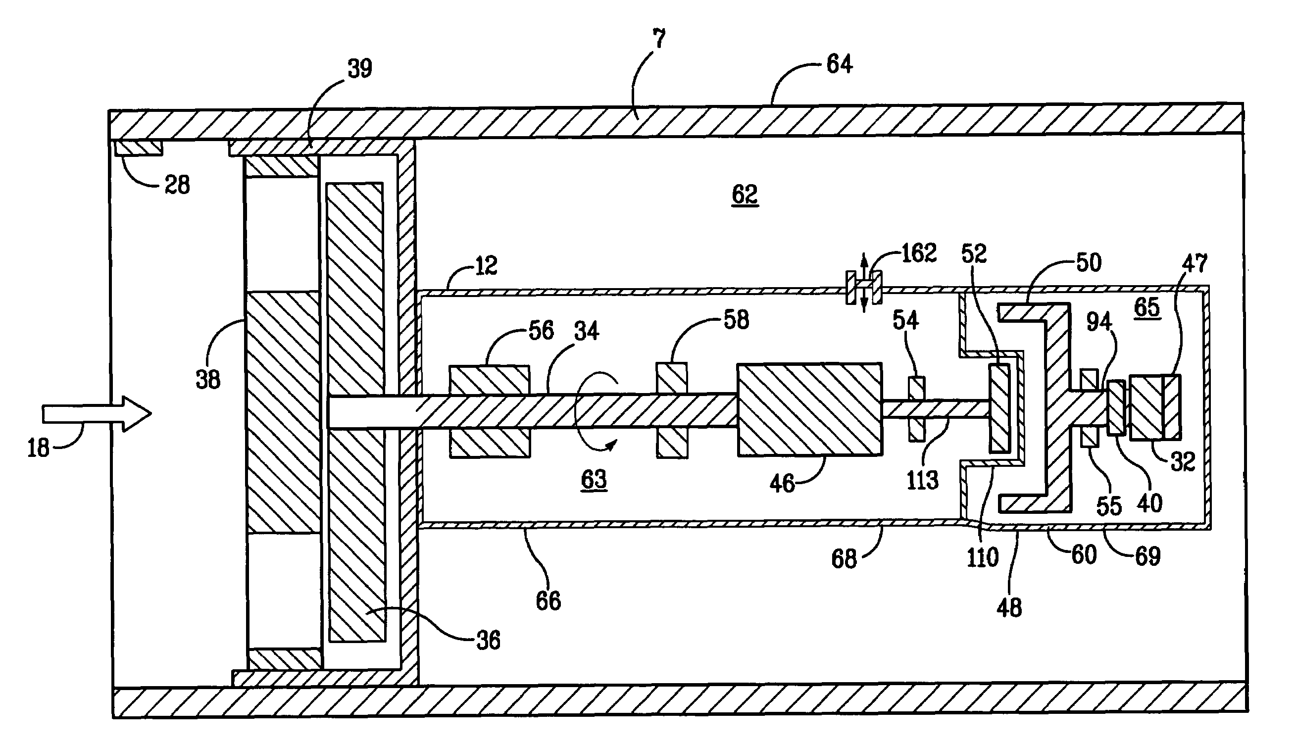
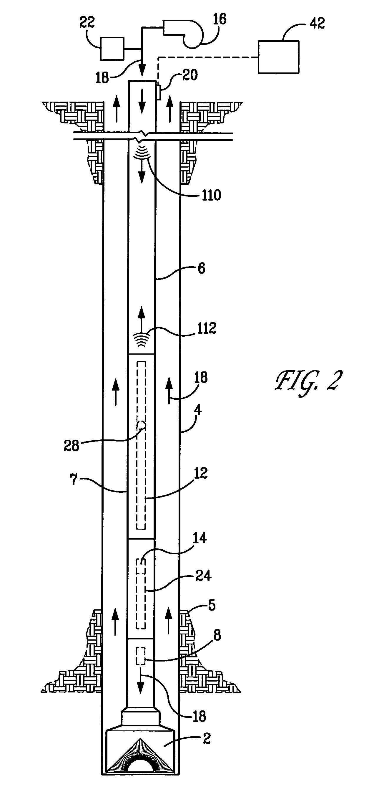
[0031]A drilling operation incorporating a mud pulse telemetry system according to the current invention is shown in FIG. 2. A drill bit 2 drills a bore hole 4 into a formation 5. The drill bit 2 is attached to a drill string 6 that, as is conventional, is formed of sections of piping joined together. As is also conventional, a mud pump 16 pumps drilling mud 18 downward through the drill string 6 and into the drill bit 2. The drilling mud 18 flows upward to the surface through the annular passage between the bore 4 and the drill string 6, where, after cleaning, it is recirculated back down the drill string by the mud pump 16. As is conventional in MWD and LWD systems, sensors 8, such as those of the types discussed above, are located in the bottom hole assembly portion 7 of the drill string 6. In addition, a surface pressure sensor 20, which may be a transducer, senses pressure pulses in the drilling mud 18. According to a preferred embodiment of the invention, a pulser device 22, s...


PUM


Abstract

A rotary pulser for transmitting information to the surface from down hole in a well by generating pressure pulses encoded to contain information. The pressure pulses travel to the surface where they are decoded so as to decipher the information. The pulser includes housing containing a stator forming passages through which drilling fluid flows on its way to the drill bit, a rotor, and a replaceable wear sleeve enclosing the rotor. The rotor has blades that are capable of imparting a varying obstruction to the flow of drilling fluid through the stator passages depending on the circumferential orientation of the rotor, so that rotation of the rotor by a motor generates the encoded pressure pulses. The rotor is located downstream of the stator and the rotor blades are shaped so that when the motor is not in operation, a hydrodynamic opening torque is imparted to the rotor that tends to rotate the rotor blades away from the circumferential orientation that results in the maximum obstruction and toward the circumferential orientation that results in the minimum obstruction. A torsion spring provides a mechanical force that also tends to rotate the rotor into the orientation that provides the minimum flow obstruction.

Description

FIELD OF THE INVENTION[0001]The current invention is directed to an improved rotary pulser for transmitting information from a down hole location in a well to the surface, such as that used in a mud pulse telemetry system employed in a drill string for drilling an oil well.BACKGROUND OF THE INVENTION[0002]In underground drilling, such as gas, oil or geothermal drilling, a bore is drilled through a formation deep in the earth. Such bores are formed by connecting a drill bit to sections of long pipe, referred to as a “drill pipe,” so as to form an assembly commonly referred to as a “drill string” that extends from the surface to the bottom of the bore. The drill bit is rotated so that it advances into the earth, thereby forming the bore. In rotary drilling, the drill bit is rotated by rotating the drill string at the surface. In directional drilling, the drill bit is rotated by a down hole mud motor coupled to the drill bit; the remainder of the drill string is not rotated during dril...

Claims


Application Information

Patent Timeline
Patent Type & Authority Patents(United States)
IPC IPC(8): E21B47/18H04H9/00H04H60/31
CPCE21B47/182E21B47/20E21B47/18
Inventor PERRY, CARL A.BURGESS, DANIEL E.TURNER, WILLIAM E.
Owner APS TECH
Why Eureka
Try Eureka