
Branch prediction and other processor improvements using FIFO for bypassing certain processor pipeline stages

a technology of fifo and processor, applied in the field of information and communication, can solve problems such as invalidation or flushing, waste of time and power, and add software and hardware in systems,

Active Publication Date: 2008-02-05
TEXAS INSTR INC
View PDF16 Cites 34 Cited by
  • Summary
  • Abstract
  • Description
  • Claims
  • Application Information

AI Technical Summary

Benefits of technology

This approach enhances branch prediction accuracy and reduces power dissipation, leading to improved performance and efficiency in microprocessors by minimizing the flushing of pipeline stages and optimizing instruction execution.

Problems solved by technology

These potentially mean added software and hardware in systems where cost and power dissipation are already important concerns.
Branches present a challenge to pipeline processing of instructions.
If the instructions currently being executed earlier in the pipeline are the wrong ones, the operations performed in the earlier pipestages are irrelevant and need to be invalidated or flushed.
These irrelevant operations waste time and power.
The flush operation also consumes time and power.
A pipeline flush entails a substantial amount of wasted time and degrades the performance which is so important in a high-performance microprocessor.
Also, multiple instructions are “speculatively” issued to one or more pipelines, meaning that the instructions are issued on the uncertain assumption that the branch predictions are correct.
In consequence, the importance of accurate branch prediction is increasing because ever more pipeline stages are in danger of being subject to wasted operations (“bubbles”) if any branch predictions are incorrect.
However, the prior art approaches still fall short of the goal of perfect branch prediction imposing power dissipation problems, and introduce complexities for the pipestages, and limit processor speed.

Method used


Image

  • Branch prediction and other processor improvements using FIFO for bypassing certain processor pipeline stages
  • Branch prediction and other processor improvements using FIFO for bypassing certain processor pipeline stages
  • Branch prediction and other processor improvements using FIFO for bypassing certain processor pipeline stages

Examples


Embodiment Construction

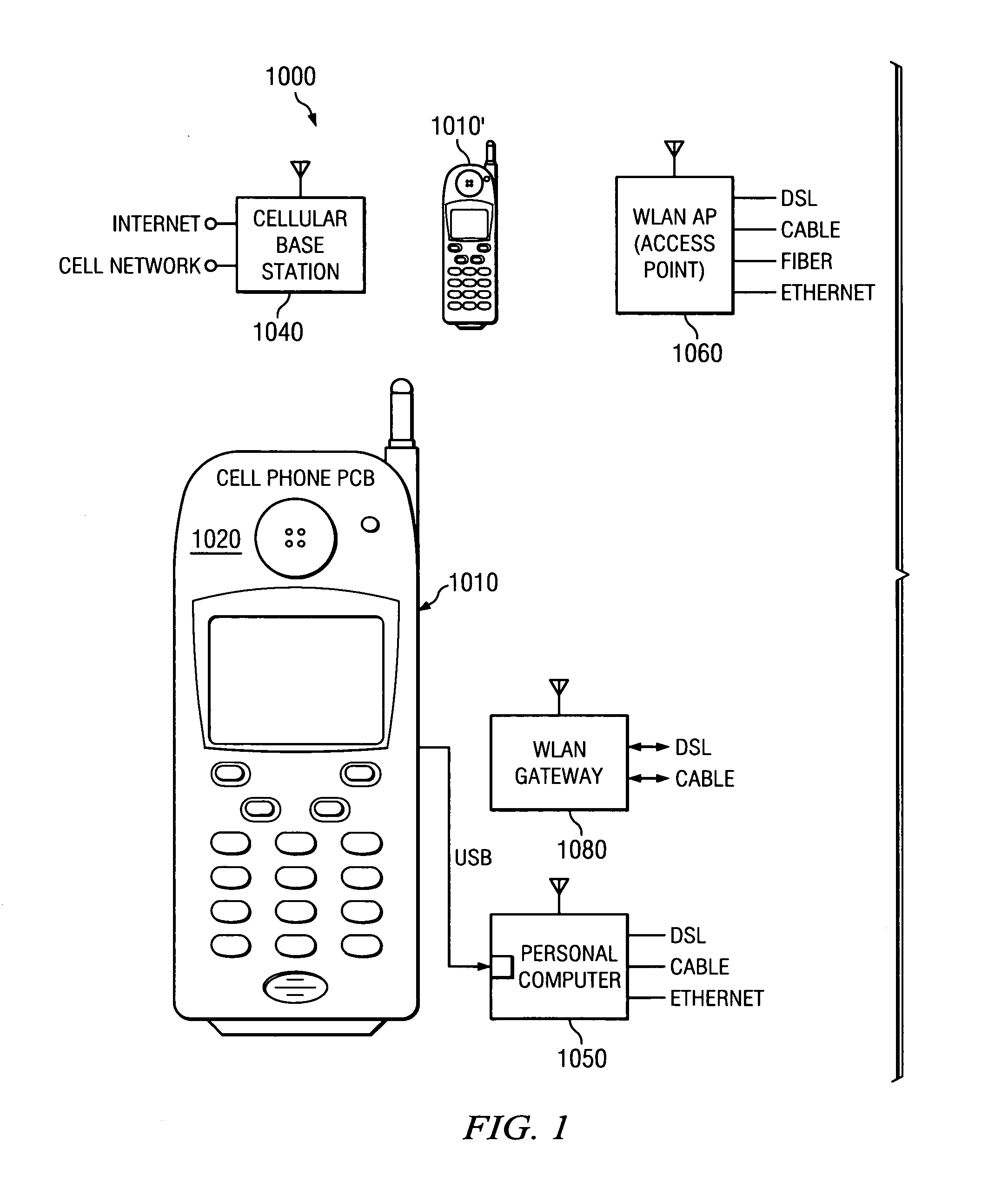
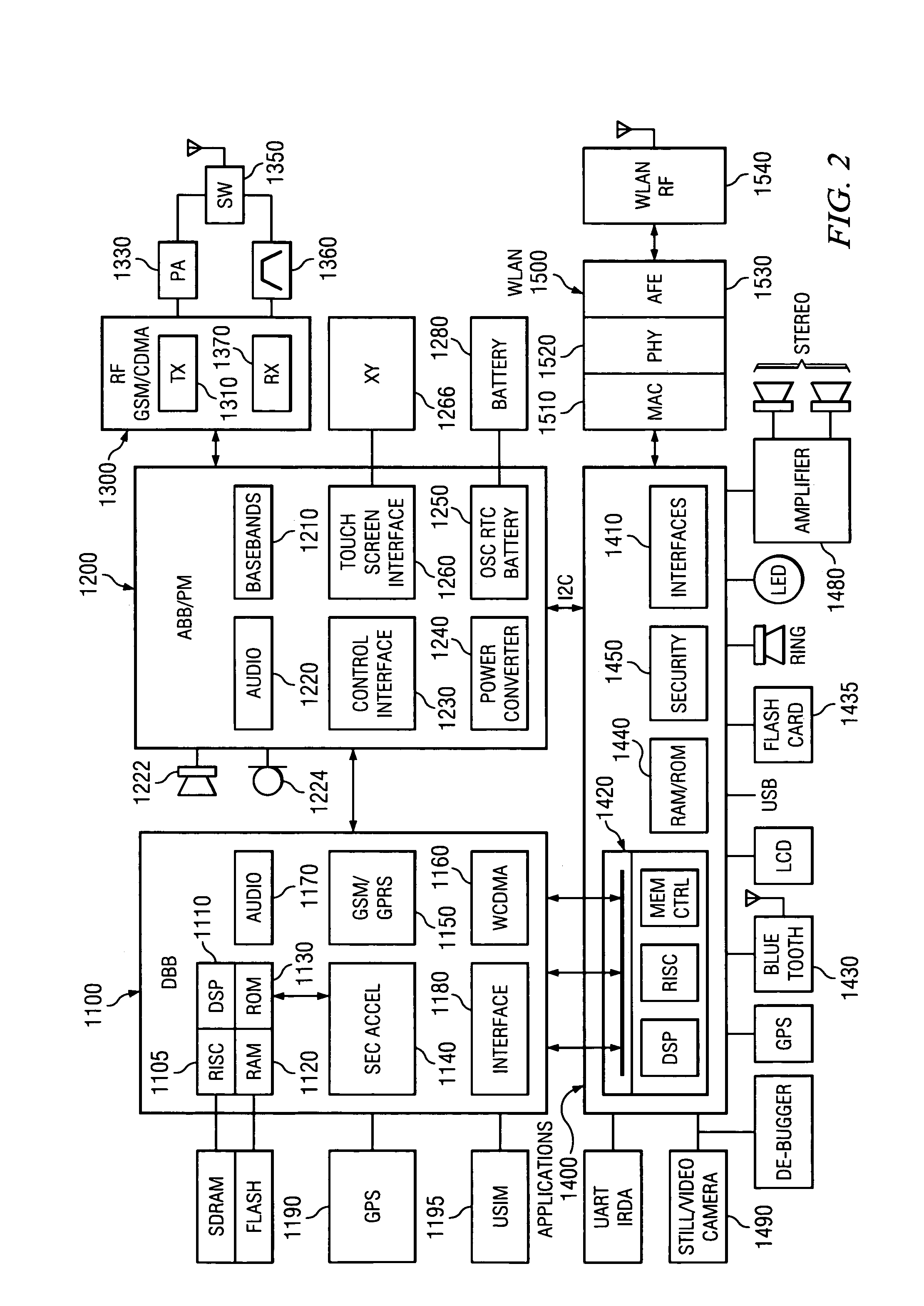
[0036]In FIG. 1, an improved communications system 1000 has system blocks with increased metrics of features per watt of power dissipation, cycles per watt, features per unit cost of manufacture, and greater throughput of instructions per cycle, among other advantages.

[0037]Any or all of the system blocks, such as cellular mobile telephone and data handsets 1010 and 1010′, a cellular (telephony and data) base station 1040, a WLAN AP (wireless local area network access point, IEEE 802.11 or otherwise) 1060, a Voice WLAN gateWay 1080 with user voice over packet telephone, and a voice enabled personal computer (PC) 1050 with another user voice over packet telephone, communicate with each other in communications system 1000. Each of the system blocks 1010, 1010′, 1040, 1050, 1060, 1080 is provided with one or more PHY physical layer blocks and interfaces as selected by the skilled worker in various products, for DSL (digital subscriber line broadband over twisted pair copper infrastruct...


PUM


Abstract

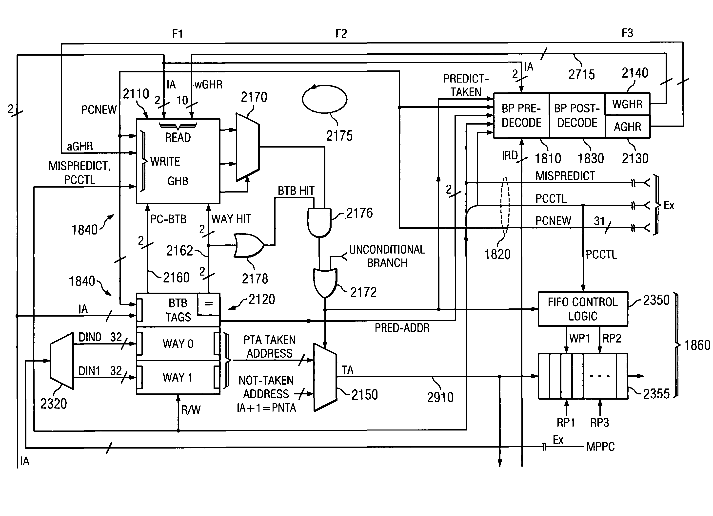
A processor (1700) including a pipeline (1710, 1740) having a fetch pipeline (1710) with branch prediction circuitry (1840) to supply respective predicted taken target addresses for branch instructions, an execution pipeline (1740) with a branch execution circuit (1870), and storage elements (in 1860) and control logic (2350) operable to establish a first-in-first-out (FIFO) circuit (1860) with a write pointer WP1 and a read pointer RP1. The control logic (2350) is responsive to the branch prediction circuitry (1840) to write a predicted taken target address to a storage element (in 1860) identified by the write pointer (WP1) and the predicted taken target address remains stationary therein. The FIFO circuit (1860) bypasses a plurality of pipestages between the branch prediction circuitry (1840) and the branch execution circuit (1870). The control logic (2350) is operable to read a predicted taken target address (PTTPCA) from a storage element (in 1860) identified by the read pointer RP1.

Description

CROSS-REFERENCE TO RELATED APPLICATIONS[0001]This application is related to provisional U.S. Patent Application Ser. No. 60 / 605,846, filed Aug. 30, 2004, titled “Global History Register Optimizations,” for which priority under 35 U.S.C. 119(e)(1) is hereby claimed and which is hereby incorporated herein by reference.[0002]This application is related to provisional U.S. Patent Application Ser. No. 60 / 605,837, filed Aug. 30, 2004, titled “Branch Target FIFO and Branch Resolution in Execution Unit,” for which priority under 35 U.S.C. 119(e)(1) is hereby claimed and which is hereby incorporated herein by reference.[0003]This application is related to provisional U.S. Patent Application Ser. No. 60 / 605,836 filed Aug. 30, 2004, titled “Dual Pipeline Multi-Threading,” for which priority under 35 U.S.C. 119(e) (1) is hereby claimed and which is hereby incorporated herein by reference.[0004]This application is co-filed so that the present U.S. non-provisional patent application “Processes, C...

Claims


Application Information

Patent Timeline
Patent Type & Authority Patents(United States)
IPC IPC(8): G06F9/44
CPCG06F9/3016G06F9/30167G06F9/3802G06F9/382G06F9/3824G06F9/3826G06F9/383G06F9/3848G06F9/3875G06F9/30149G06F9/30196G06F9/3806G06F9/3816
Inventor TRAN, THANG
Owner TEXAS INSTR INC
Learn More