Compact x-ray source and panel

a x-ray source and panel technology, applied in the field of x-ray generating systems, can solve the problems of large system size, large system volume, cumbersome, etc., and achieve the effect of small volume, small difference in potential, and short drift distance/spacing

Active Publication Date: 2008-02-12
LAWRENCE LIVERMORE NAT SECURITY LLC
View PDF10 Cites 36 Cited by
  • Summary
  • Abstract
  • Description
  • Claims
  • Application Information

AI Technical Summary

Benefits of technology

[0006]The present invention is generally directed to a compact x-ray source having an electron source, an x-ray conversion target, and a multilayer insulator separating the electron source a short distance away from the x-ray conversion target to establish a short drift distance / spacing therebetween. Short separation distances between a cathode and anode can produce surface flashovers in insulators when high voltage energies are applied therebetween, especially at the high voltages necessary for x-ray production, e.g. 150 kV. The multilayer insulator used in the present invention is of a type similar to that disclosed in U.S. Pat. No. 6,331,194, designed to inhibit such surface flashover between the closely spaced electrodes and thereby enable large differences in potential to be applied therebetweeen (typically over 100 kV / cm). In this manner, the use of the multilayer insulator enables the substantial reduction of the scale size of a unit x-ray source into an extremely compact structure which may be 10 to 100 times less the volume of existing technology, with an attendant reduction in cost. Similarly, a plurality of such unit x-ray sources arranged as a broad-area array of an x-ray source panel can also realize substantial reduction in size in that the panel depth is substantially smaller / thinner than it is tall or wide.

Problems solved by technology

The problem, however, with the scanning technique utilized in current broad-beam x-ray sources is the large and bulky size typically associated with such systems due to the geometry of the scanning arrangement.
Due to this geometric limitation, the dimensions of the vacuum envelope of the x-ray source (spanning between the hot filament to target) consumes a significant portion of the overall system size, making the system large, cumbersome, and usually very expensive.
Because designers cannot easily anticipate the wide variety of objects a user would seek to image, and the expense of such large-scale / dimensioned systems is so significant, a “one size fits all” mentality is incorporated into the design and acquisition of very large aperture x-ray imaging systems, with the net result being a narrowed use of the technology only by larger institutions.

Method used


Image

  • Compact x-ray source and panel
  • Compact x-ray source and panel
  • Compact x-ray source and panel

Examples


Embodiment Construction

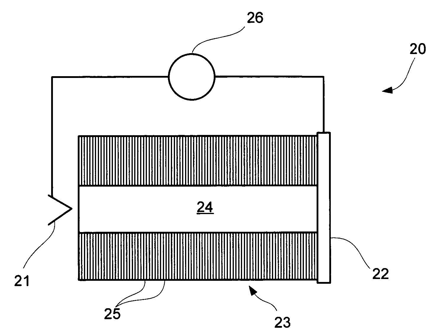
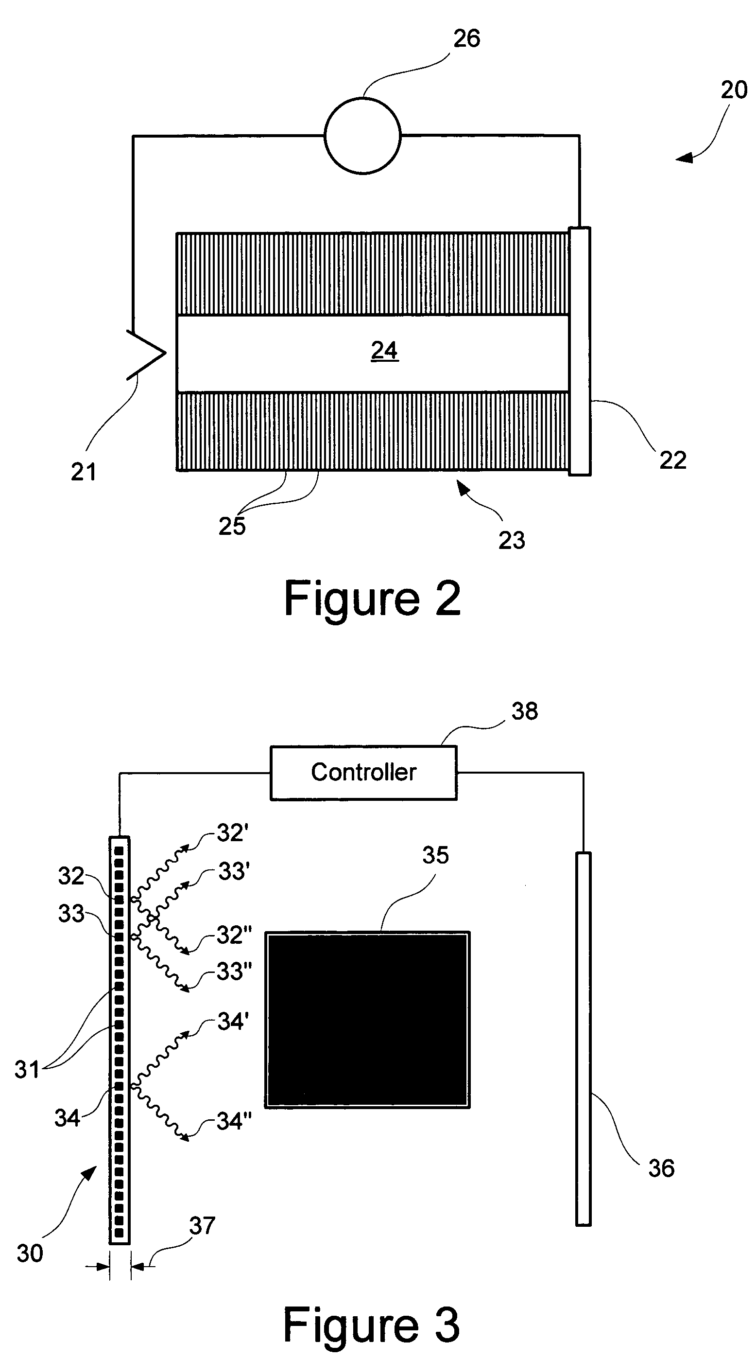
[0019]Turning now to the drawings, FIG. 2 shows a preferred embodiment of a single unit x-ray source of the present invention, generally indicated at reference character 20. The x-ray source 20 is shown having an electron source 21 for producing electrons, an x-ray conversion target 22 capable of generating an x-ray beam when incidenced by electrons, an insulator 23 separating the electron source 21 and the x-ray conversion target 22, and a power supply 26 electrically connected to the electron source 21 (cathode) and x-ray conversion target 22 (anode) to produce a voltage potential, i.e. an acceleration gradient, in the drift space 24 therebetween which accelerates electrons toward the x-ray conversion target 22.

[0020]The electron source 21 is preferably a heated filament which emits electrons when hot. In the alternative, various types of electron sources which are individually controllable may be utilized, such as for example, thin film ferroelectric emitters, pulsed hybrid diamo...


PUM


Abstract

A compact, self-contained x-ray source, and a compact x-ray source panel having a plurality of such x-ray sources arranged in a preferably broad-area pixelized array. Each x-ray source includes an electron source for producing an electron beam, an x-ray conversion target, and a multilayer insulator separating the electron source and the x-ray conversion target from each other. The multi-layer insulator preferably has a cylindrical configuration with a plurality of alternating insulator and conductor layers surrounding an acceleration channel leading from the electron source to the x-ray conversion target. A power source is connected to each x-ray source of the array to produce an accelerating gradient between the electron source and x-ray conversion target in any one or more of the x-ray sources independent of other x-ray sources in the array, so as to accelerate an electron beam towards the x-ray conversion target. The multilayer insulator enables relatively short separation distances between the electron source and the x-ray conversion target so that a thin panel is possible for compactness. This is due to the ability of the plurality of alternating insulator and conductor layers of the multilayer insulators to resist surface flashover when sufficiently high acceleration energies necessary for x-ray generation are supplied by the power source to the x-ray sources.

Description

[0001]The United States Government has rights in this invention pursuant to Contract No. W-7405-ENG-48 between the United States Department of Energy and the University of California for the operation of Lawrence Livermore National Laboratory.I. FIELD OF THE INVENTION[0002]The present invention relates to x-ray generating systems, and more particularly to a compact x-ray source having a substantially minimized drift distance, and a thin broad-area x-ray source panel comprising a plurality array of such compact x-ray sources.II. BACKGROUND OF THE INVENTION[0003]Broad beam x-ray sources, such as shown in FIG. 1 at reference character 10, are commonly known, and typically utilize a scanning technique of a highly collimated electron beam to develop a line or raster scanned pattern. In particular, these broad beam X-ray sources include a hot filament cathode 11 to produce electrons, and a positively-charged anode 16, i.e. an x-ray conversion target such as tungsten, spaced from the catho...

Claims


Application Information

Patent Timeline
Patent Type & Authority Patents(United States)
IPC IPC(8): H01J35/00
CPCH01J35/30
Inventor SAMPAYON, STEPHEN E.
Owner LAWRENCE LIVERMORE NAT SECURITY LLC
Why Eureka
Try Eureka