Wind turbine pitch bearing and method

a technology of pitch bearing and wind turbine, which is applied in the direction of wind energy generation, liquid fuel engine components, non-positive displacement fluid engine, etc., can solve the problems of high manufacturing cost, assembly and repair, and achieve the effect of convenient economical manufacturing

Inactive Publication Date: 2008-02-19
KAYDON CORP
View PDF15 Cites 50 Cited by
  • Summary
  • Abstract
  • Description
  • Claims
  • Application Information

AI Technical Summary

Benefits of technology

[0004]One aspect of the present invention is a wind electric turbine of the type having a rotor hub supporting at least one radially extending blade, and a pitch drive for axially pivoting the blade between different pitch angles. The wind turbine includes a pitch bearing, comprising an annularly-shaped first bearing ring operably connected with the blade, and including a first raceway groove, and an annularly-shaped second bearing ring operably connected with the rotor hub, configured for mating engagement with the first bearing ring, and including a second raceway groove aligned with the first raceway groove. A plurality of rolling elements are disposed in the first and second raceway grooves to rotatably interconnect the first and second bearing rings. A gear segment is formed on one of the first and second bearing rings, and engages the pitch drive to pivot the blade axially between the different pitch angles. The gear segment has an accurate measure of less than 200 degrees to facilitate economical manufacture.
[0005]Another aspect of the present invention is a method for making a wind electric turbine of the type having a rotor hub supporting at least one radially extending blade, and a pitch drive for axially pivoting the blade between different pitch angles. The method includes forming an annularly-shaped first pitch bearing ring with a first raceway groove, and an annularly-shaped second pitch bearing ring with a second raceway groove. The method further includes positioning one of the first and second pitch bearing rings within the other, such that the first raceway groove aligns with the second raceway groove. The method further includes forming a plurality of rolling elements shaped for close reception in the first and second raceway grooves, and positioning the rolling elements in the first and second raceway grooves in a predetermined circumferentially-shaped arrangement to rotatably interconnect the first and second pitch bearing rings. The method further includes forming a gear segment on one of the first and second pitch bearing rings with an accurate measure of less than 200 degrees to facilitate economical manufacture, and operably connecting the blade with one of the first and second pitch bearing rings, and the rotor hub with the other of the first and second pitch bearing rings. Further, the method includes engaging the pitch drive with the gear segment to pivot the blade axially between the different pitch angles.
[0006]Yet another aspect of the present invention is a pitch bearing for wind turbines of the type having a rotor hub supporting at least one radially extending blade, and a pitch drive for axially pivoting the blade between different pitch angles. The pitch bearing includes an annularly-shaped first bearing ring configured for operable connection with the blade, and including a first raceway groove, as well as an annularly-shaped second bearing ring configured for operable connection with the rotor hub, matingly engaging the first bearing ring, and including a second raceway groove aligned with the first raceway groove in the first bearing ring. A plurality of rolling elements are disposed in the first and second raceway grooves to rotatably interconnect the first and second bearing rings. A gear segment is formed on one of the first and second bearing rings, and is configured to engage the pitch drive to pivot the blade axially between the different pitch angles. The gear segment has an accurate measure of less than 200 degrees to facilitate economical manufacture.
[0007]Another aspect of the present invention is to provide a wind turbine pitch bearing which is efficient in use, economical to manufacture, capable of a long operating life and particularly well adapted for the proposed use. The pitch bearing is capable of use in both high or low wind speed applications, as well as land based or off shore installations.

Problems solved by technology

While such prior art pitch bearings have proven to be quite functional, they are expensive to manufacture, assemble and repair.

Method used


Image

  • Wind turbine pitch bearing and method
  • Wind turbine pitch bearing and method
  • Wind turbine pitch bearing and method

Examples


Embodiment Construction

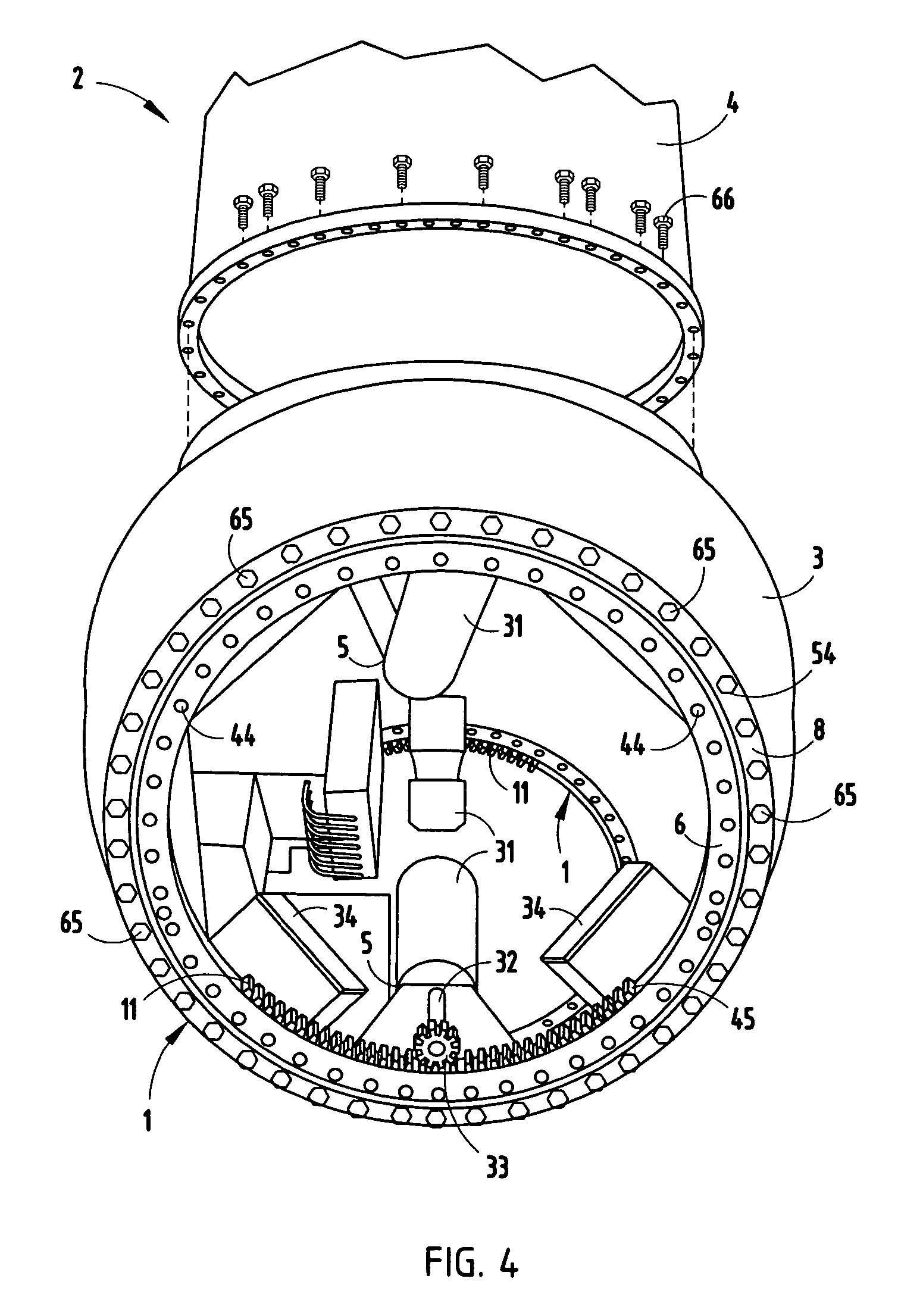
[0019]For purposes of description herein, the terms “upper”, “lower”, “right”, “left”, “rear”, “front”, “vertical”, “horizontal”, and derivatives thereof shall relate to the invention as oriented in FIG. 4. However, it is to be understood that the invention may assume various alternative orientations and step sequences, except where expressly specified to the contrary. It is also to be understood that the specific devices and processes illustrated in the attached drawings, and described in following specification, are simply exemplary embodiments of the inventive concepts defined in the appended claims. Hence, the specific dimensions and other physical characteristics relating to the embodiments disclosed herein are not to be considered as limiting, unless the claims expressly state otherwise.

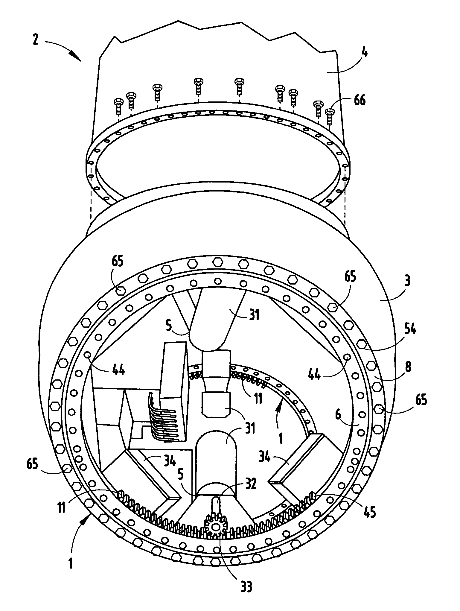
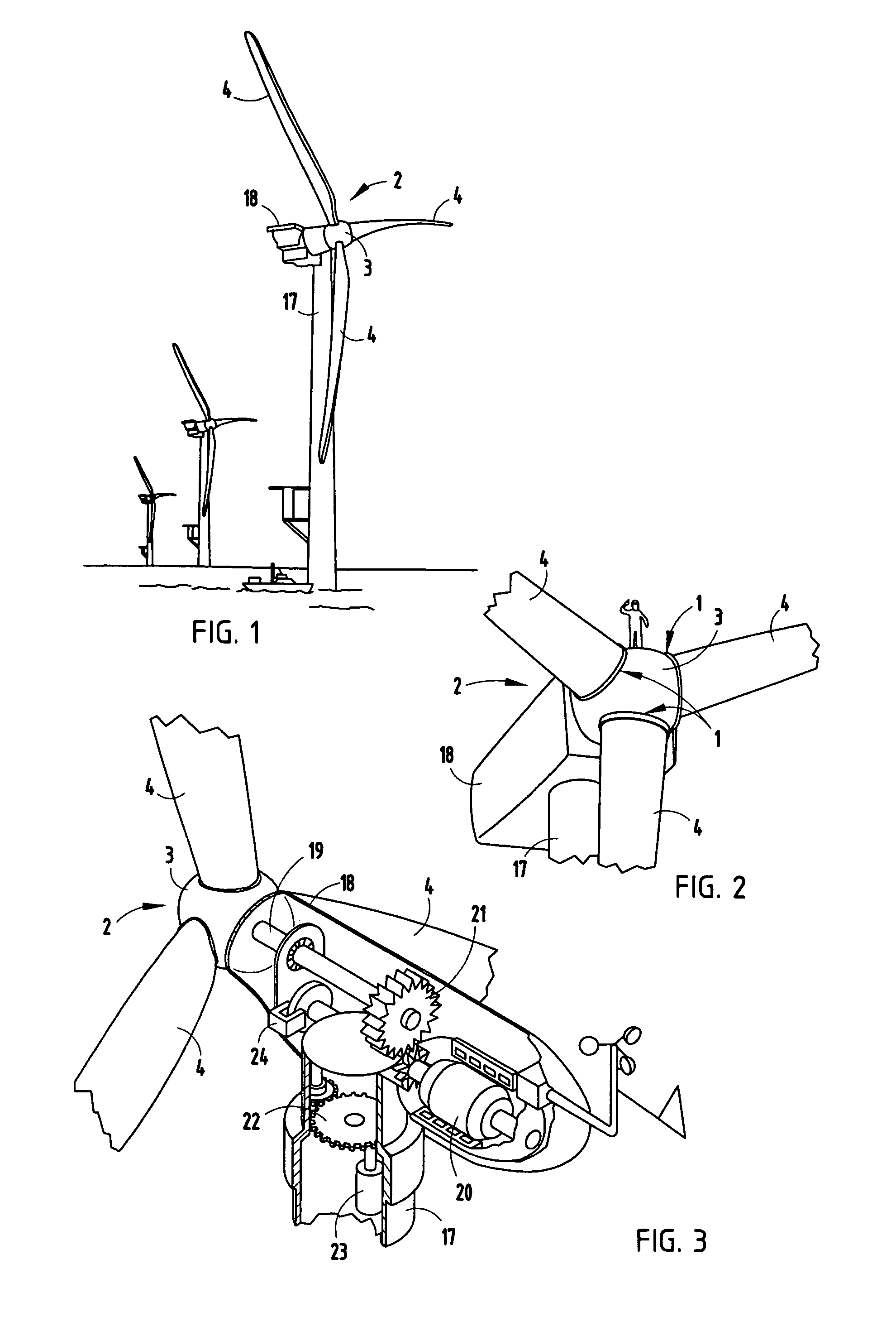
[0020]The reference numeral 1 (FIGS. 1-4) generally designates a pitch bearing embodying the present invention. Pitch bearing 1 is designed for use in conjunction with wind turbines, such as th...


PUM


Abstract

A pitch bearing and related method for wind electric turbines has an annularly-shaped first bearing ring connected with an associated wind turbine blade, and includes a first raceway groove. An annularly-shaped second bearing ring is connected with the rotor portion of the wind turbine, and includes a second raceway groove aligned with the first raceway groove. Rolling elements are positioned in the first and second raceway grooves to rotatably interconnect the two bearing rings. A gear segment is formed on one of the bearing rings, and is configured to engage a pitch drive portion of the wind turbine to pivot the blade axially between different pitch angles. The gear segment has an arcuate measure of less than 200 degrees to facilitate economical manufacture.

Description

BACKGROUND OF THE INVENTION[0001]The present invention relates to wind turbines and the like, and in particular to a pitch bearing therefore.[0002]Wind turbines, such as those designed to generate electrical power, are well known in the art. Large, sophisticated wind turbines typically include a mechanism for axially pivoting the turbine blade relative to the rotor hub to shift the blade between different pitch angles to achieve maximum efficiency. Large pitch bearings are required to pivotally mount the turbine blades to the rotor hubs, which must be made to precise specifications and meet expecting standards for such applications. Furthermore, the pitch bearings are typically equipped with a full circle ring gear to facilitate rotating the turbine blades through associated geared pitch drives. While such prior art pitch bearings have proven to be quite functional, they are expensive to manufacture, assemble and repair.[0003]Hence, it would be clearly advantageous to provide a pitc...

Claims


Application Information

Patent Timeline
Patent Type & Authority Patents(United States)
IPC IPC(8): B63H3/00
CPCF03D7/0224F03D11/0008F16C19/163F16C19/181F16C33/586F05B2240/50F16C2300/14Y02E10/721Y02E10/722Y02E10/723Y10S415/908F16C2360/31F16C2361/61F16C19/166F03D80/70Y02E10/72Y02P70/50
Inventor HANSEN, SCOTT A.VANLANGEVELEDE, DAVID J.
Owner KAYDON CORP
Why Eureka
Try Eureka