Apparatus and methods for sealing a vascular puncture

a technology of vascular puncture and apparatus, applied in the field of apparatus and methods for sealing punctures, can solve the problems of time-consuming and expensive procedures, requiring as much as an hour of medical professionals' time, and uncomfortable for patients

Active Publication Date: 2008-02-19
ACCESS CLOSURE INC
View PDF150 Cites 328 Cited by
  • Summary
  • Abstract
  • Description
  • Claims
  • Application Information

AI Technical Summary

Benefits of technology

[0011]The inner member may include proximal and distal ends, the distal end being coupled to the distal end of the expandable member. Preferably, the inner member is slidably disposed within the lumen of the outer member for moving the distal end of the expandable member towards or away from the proximal end of the expandable member. An element, e.g., a piston, may be coupled to the inner member that includes a surface exposed to the lumen such that, when fluid is introduced into the lumen, fluid pressure from the fluid may push against the surface, causing the inner member to move proximally relative to the outer member. Because the distal end of the inner member is coupled to the distal end of the balloon, this proximal movement of the inner member may move the distal end of the expandable member towards the proximal end of the expandable member, thereby shortening the expandable member as it expands.
[0013]Thus, the expandable member may have a length that may shorten as the expandable member is expanded, i.e., as fluid is delivered into the lumen, and that may lengthen as the expandable member is collapsed, i.e., as fluid is withdrawn from the lumen. In one embodiment, the expandable member may at least partially evert, i.e., the proximal and distal ends may partially enter the interior of the expandable member as it expands towards the expanded state.
[0016]The apparatus may be introduced into the puncture with the expandable member in a collapsed state until the expandable member is disposed within the body lumen. For example, the apparatus may be introduced through a lumen of an introducer sheath or other tubular member previously placed in the puncture. Fluid may be introduced into the outer member to expand the expandable member to an expanded state, the fluid causing the inner member to move proximally relative to the outer member to shorten the length of the expandable member as it expands.
[0020]In one embodiment, an introducer sheath may be introduced through the puncture into the body lumen, and the apparatus may be introduced into the puncture through the introducer sheath. The sealing material may be introduced into the puncture through the introducer sheath, e.g., between the outer member and the sheath. Preferably, the introducer sheath may be withdrawn from the puncture as the sealing compound is introduced into the puncture, e.g., to substantially fill the puncture with the sealing compound.
[0024]An element, e.g., a piston, may be coupled to the inner member that includes a surface exposed to the lumen such that, when fluid is introduced into the lumen, fluid pressure from the fluid may push against the surface, causing the inner member to move proximally. This causes the distal end of the expandable member to move towards the proximal end of the expandable member, thereby shortening the expandable member as it expands. Conversely, when the fluid is evacuated to collapse the expandable member, the inner member may move distally, thereby lengthening the expandable member as it is collapsed.
[0027]Fluid may be removed from the expandable member, thereby collapsing the expandable member to the collapsed state and causing the expandable member to extend distally as it collapses. With the expandable member in the collapsed state, the elongate member may be withdrawn from the tract, e.g., through the hydrogel after the hydrogel has at least partially solidified. Optionally, the introducer sheath may be withdrawn from the tract as the polymer components are introduced into the tract, e.g., to substantially fill the tract with the hydrogel.

Problems solved by technology

This procedure, however, may be time consuming and expensive, requiring as much as an hour of a medical professional's time.
It is also uncomfortable for the patient, and may require the patient to remain immobilized in the operating room, catheter lab, or holding area.
In addition, a risk of hematoma exists from bleeding before hemostasis occurs.
The disclosed plug, however, may be difficult to position properly with respect to the vessel, which may be significant since it is generally undesirable to expose the collagen material within the bloodstream where it may float downstream and cause an embolism.

Method used


Image

  • Apparatus and methods for sealing a vascular puncture
  • Apparatus and methods for sealing a vascular puncture
  • Apparatus and methods for sealing a vascular puncture

Examples


Embodiment Construction

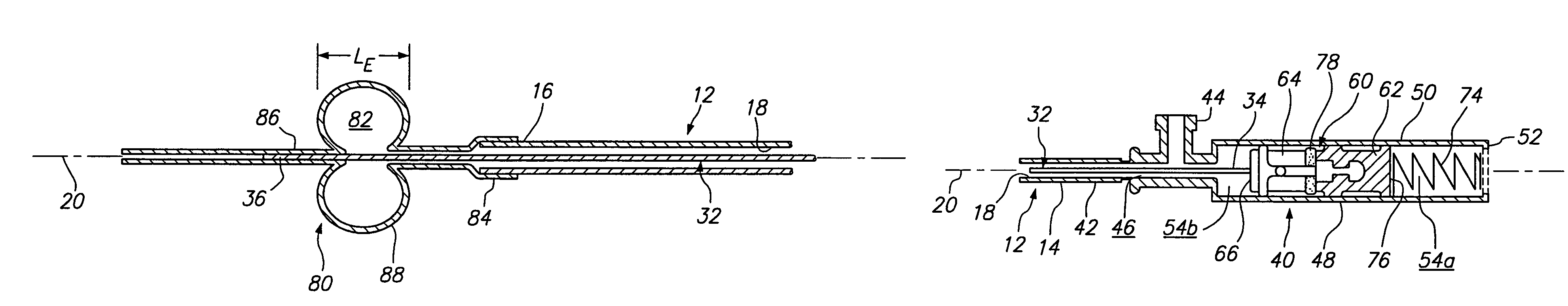
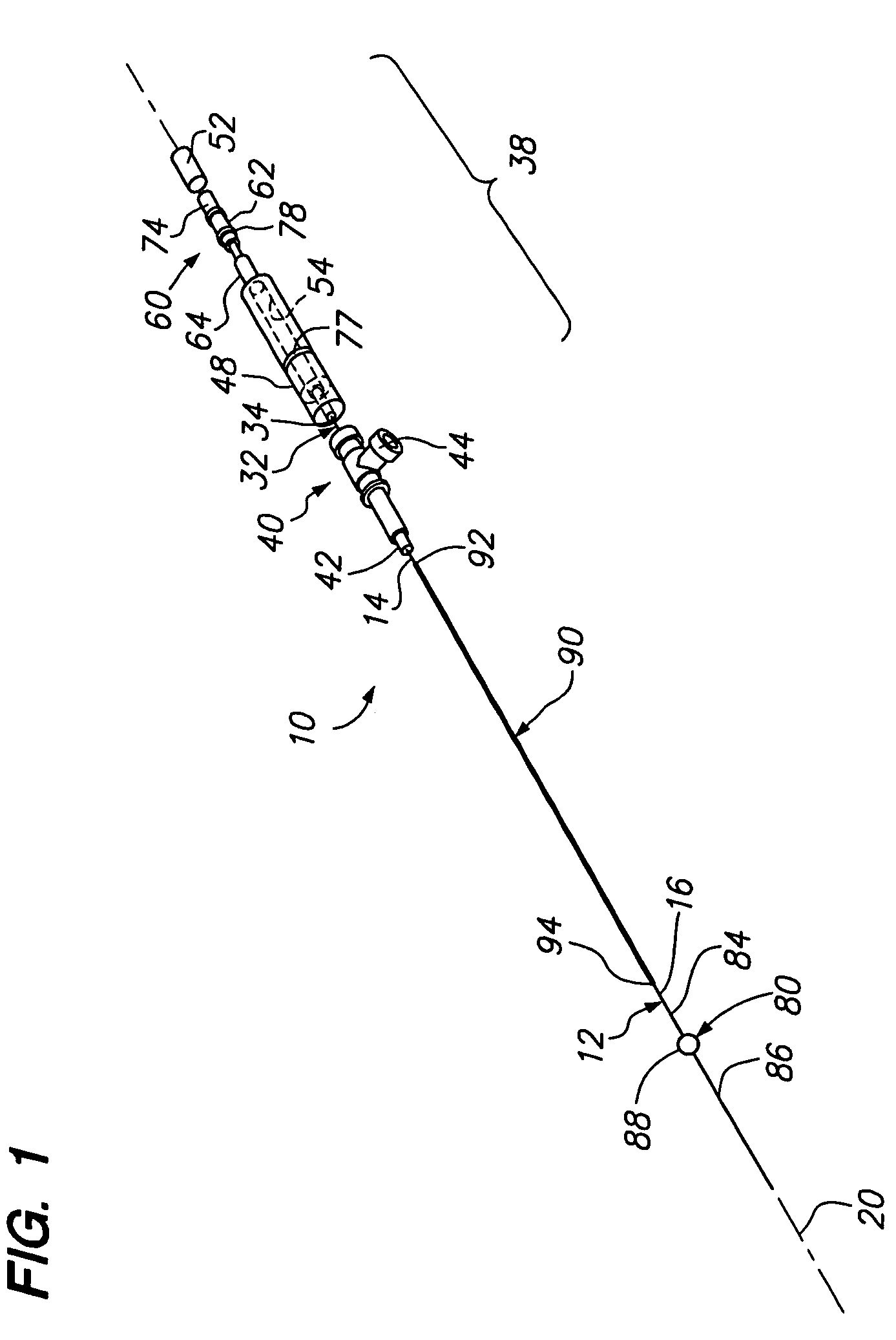
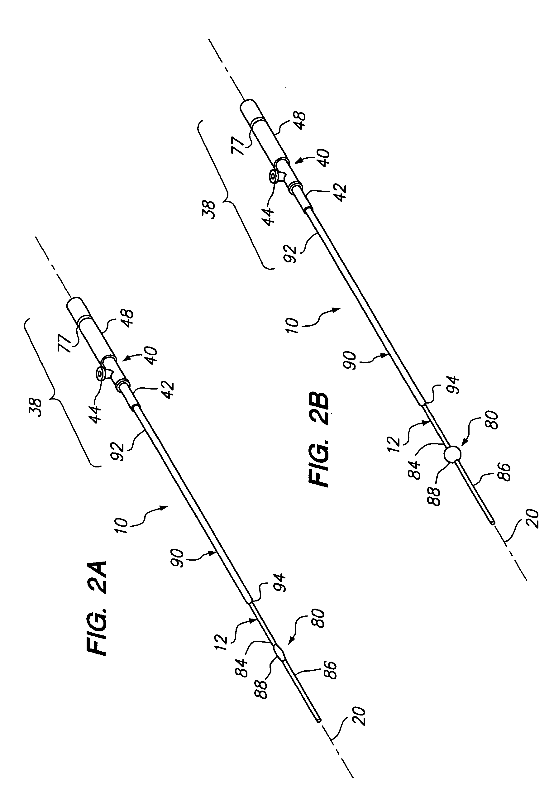
[0038]Turning to the drawings, FIGS. 1-6 show a preferred embodiment of an apparatus 10 for sealing a puncture extending through tissue and / or communicating with a body lumen (not shown). Generally, the apparatus 10 includes an outer member 12, an inner member 32 slidably coupled to the outer member 12 (best seen in FIGS. 3A, 3B, and 5), a hub subassembly 38 or other mechanism for biasing the inner member 32 relative to the outer member 12, and a balloon or other expandable member 80 coupled to the inner and outer members 32, 12. Optionally, the apparatus 10 may include an outer sleeve 90 that may at least partially cover the outer member 12.

[0039]With particular reference to FIGS. 1, 3A, and 3B, the outer member 12 may be an elongate tubular body including a proximal end 14, a distal end 16, and a lumen 18 extending therebetween (shown in FIGS. 3A, 3B, and 5), thereby defining a longitudinal axis 20. The outer member 12 may be flexible, semi-rigid, or rigid, e.g., having a uniform ...


PUM


Abstract

An apparatus for sealing a puncture communicating with a blood vessel includes an inner member slidable within an outer member, and a balloon coupled to distal ends of the inner and outer members. A proximal end of the outer member includes a port for delivering fluid into the balloon, and a cylinder that communicates with the port. A piston coupled to the inner member is slidable and biased to move distally within the cylinder. The apparatus is introduced into the puncture until the collapsed balloon is disposed within the vessel. Fluid is introduced into the port, moving the inner member proximally to shorten the balloon as it expands. The balloon is withdrawn to seal the puncture, and a hydrogel is introduced into the puncture. Fluid is removed via the port, moving the inner member distally to extend the balloon as it collapses, and the apparatus is withdrawn from the puncture.

Description

FIELD OF THE INVENTION[0001]The present invention relates generally to apparatus and methods for sealing punctures in a body, and more particularly, to apparatus and methods for sealing a vascular puncture extending through tissue into a blood vessel and to apparatus and methods for delivering a sealing compound into a percutaneous puncture extending from a patient's skin to a blood vessel or other body lumen to seal the puncture.BACKGROUND[0002]Apparatus and methods are known for accessing a patient's vasculature percutaneously, e.g., to perform a procedure within the vasculature, and for sealing the puncture that results after completing the procedure. For example, a hollow needle may be inserted through a patient's skin and overlying tissue into a blood vessel. A guide wire may be passed through the needle lumen into the blood vessel, whereupon the needle may be removed. An introducer sheath may then be advanced over the guide wire into the vessel, e.g., in conjunction with or su...

Claims


Application Information

Patent Timeline
Patent Type & Authority Patents(United States)
IPC IPC(8): A61B17/08A61B17/00A61F2/958
CPCA61B17/0057A61B17/00491A61B2017/00557A61B2017/00637A61B2017/0065A61M25/1018A61M2025/0681A61M25/10182A61M25/10187
Inventor KHOSRAVI, FARHADBAGAOISAN, CELSO J.RAMEE, STEPHEN
Owner ACCESS CLOSURE INC
Why Eureka
Try Eureka