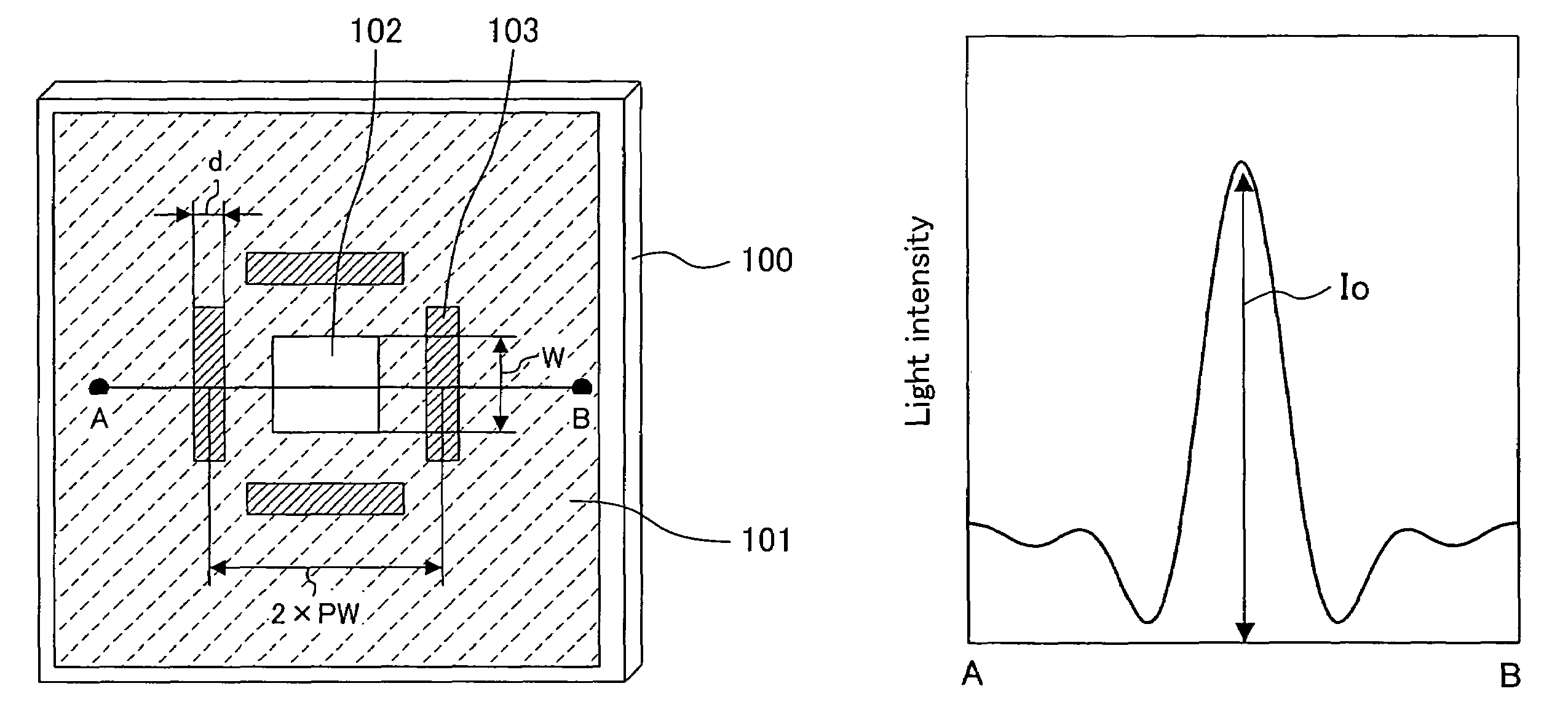
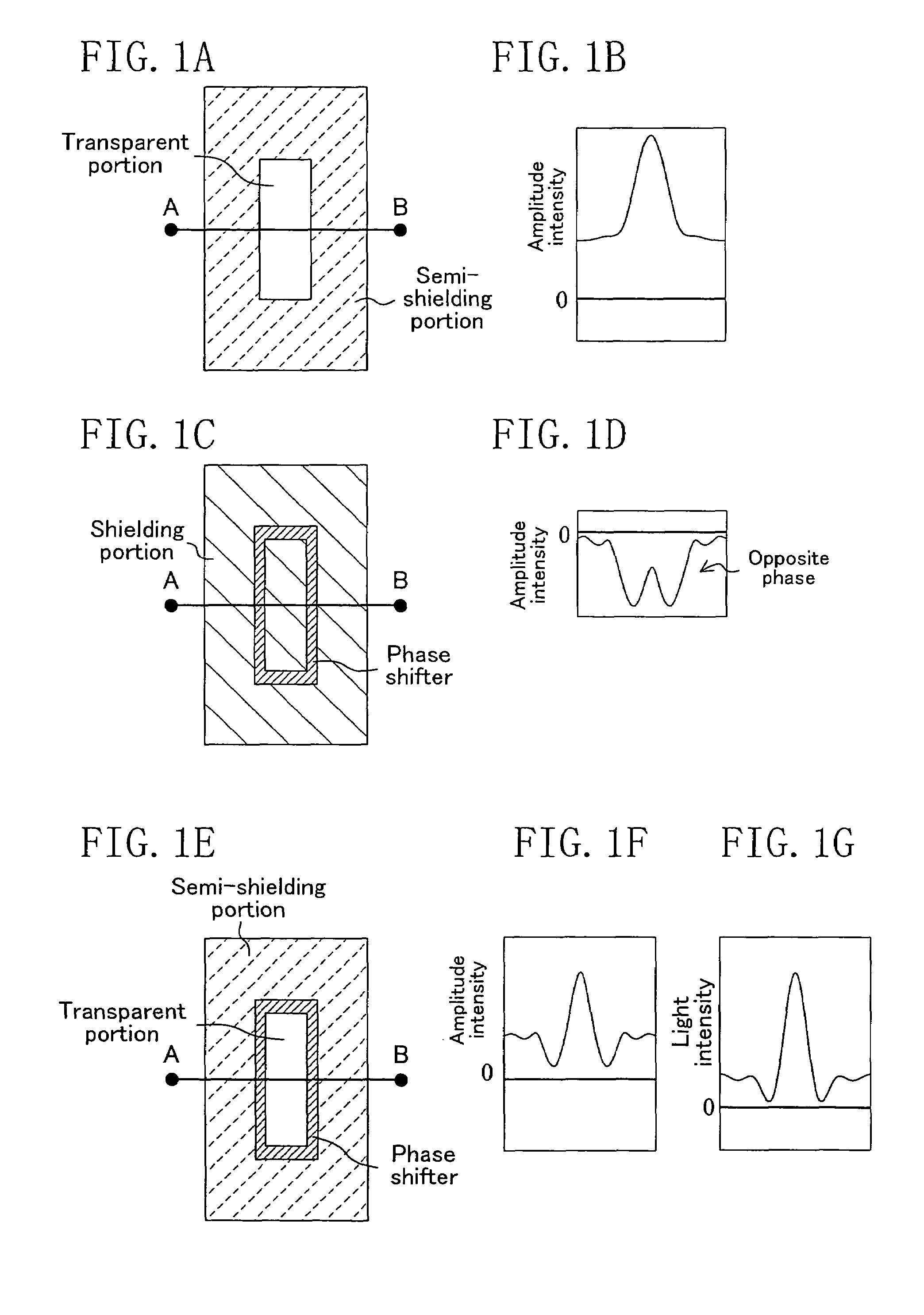
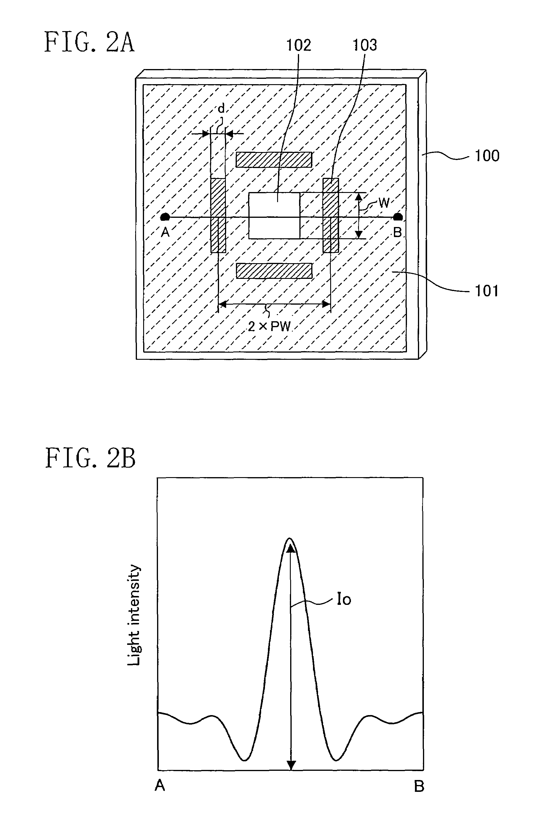
Photomask
a technology of photomasks and masks, applied in the field of photomasks, can solve the problems of degrading the contrast and the depth of focus of an image (optical image), disadvantageously small depth of focus, and unable to achieve improved contrast, so as to achieve the contrast of a light intensity distribution between transparent portions and emphasize the contrast
- Summary
- Abstract
- Description
- Claims
- Application Information
AI Technical Summary
Benefits of technology
Problems solved by technology
Method used
Image
Examples
embodiment 1
Modification of Embodiment 1
[0121]A photomask according to a modification of Embodiment 1 will now be described with reference to the accompanying drawings.
[0122]FIG. 7A is a plan view of the photomask of this modification. The photomask of this modification is used for forming a fine space pattern. Specifically, a desired pattern to be formed in this modification is a line-shaped fine space pattern differently from Embodiment 1 in which a desired pattern is a contact hole pattern. Herein, a line-shaped pattern means a pattern having an optically sufficiently large longitudinal dimension and more specifically means a pattern with a longitudinal dimension of 2×λ / NA or more.
[0123]As shown in FIG. 7A, on a transparent substrate 100, a semi-shielding portion 101 is formed so as to cover a sufficiently large area in the same manner as in the photomask of Embodiment 1 shown in FIG. 2A. Also, in a position in the semi-shielding portion 101 corresponding to a desired space pattern to be for...
embodiment 2
Modification of Embodiment 2
[0171]A photomask according to a modification of Embodiment 2 of the invention will now be described with reference to the accompanying drawings.
[0172]FIG. 15 is a plan view of the photomask of this modification. The photomask of this modification is used for simultaneously forming a plurality of fine line-shaped space patterns. Specifically, desired patterns to be formed in this modification are fine line-shaped space patterns differently from Embodiment 2 where the desired patterns are the contact hole patterns.
[0173]As shown in FIG. 15, on a transparent substrate 270, a semi-shielding portion 271 is formed so as to cover a sufficiently large area. Also, a transparent portion 272, a pair of transparent portions 273 and 274 and a pair of transparent portions 275 and 276 are provided in positions in the semi-shielding portion 201 corresponding to the desired space patterns to be formed on a wafer through the exposure. In this case, the transparent portion...
embodiment 3
Modification of Embodiment 3
[0214]A photomask according to a modification of Embodiment 3 of the invention will now be described with reference to the accompanying drawings.
[0215]FIG. 19 is a plan view of the photomask of this modification. The photomask of this modification is used for simultaneously forming a plurality of fine line-shaped space patterns. Specifically, desired patterns to be formed in this modification are fine line-shaped space pattern is differently from Embodiment 3 where the desired patterns are the contact hole patterns.
[0216]As shown in FIG. 19, on a transparent substrate 350, a semi-shielding portion 351 is formed so as to cover a sufficiently large area. Also, in the semi-shielding portion 351, a transparent portion 352, a pair of transparent portions 353 and 354 and a pair of transparent portions 355 and 356 are provided in positions corresponding to the desired space patterns to be formed on a wafer through the exposure. In this case, the transparent port...
PUM
| Property | Measurement | Unit |
|---|---|---|
| transmittance | aaaaa | aaaaa |
| transmittance | aaaaa | aaaaa |
| transmittance | aaaaa | aaaaa |
Abstract
Description
Claims
Application Information
 - R&D
- Intellectual Property
- Life Sciences
- Materials
- Tech Scout
- Unparalleled Data Quality
- Higher Quality Content
- 60% Fewer Hallucinations
Browse by: Latest US Patents, China's latest patents, Technical Efficacy Thesaurus, Application Domain, Technology Topic, Popular Technical Reports.
© 2025 PatSnap. All rights reserved.Legal|Privacy policy|Modern Slavery Act Transparency Statement|Sitemap|About US| Contact US: help@patsnap.com


