Eureka AIR delivers breakthrough ideas for toughest innovation challenges, trusted by R&D personnel around the world.

Filterless class D power amplifier

a filterless, power amplifier technology, applied in dc amplifiers, amplifiers, dc amplifiers with modulators/demodulators, etc., can solve the problems of increasing size and solution costs, increasing power consumption, and the kind of modulation scheme still has a problem relying on common mode voltage variation, so as to reduce common mode noise

Inactive Publication Date: 2008-02-19
AMAZION ELECTRONICS NC
View PDF12 Cites 46 Cited by
  • Summary
  • Abstract
  • Description
  • Claims
  • Application Information

AI Technical Summary

Benefits of technology

[0014]Another aspect of the invention is to provide a filterless class D audio power amplifier with high audio quality.
[0016]Another aspect of the invention is to provide a filterless class D audio power amplifier capable of reducing common mode noises.
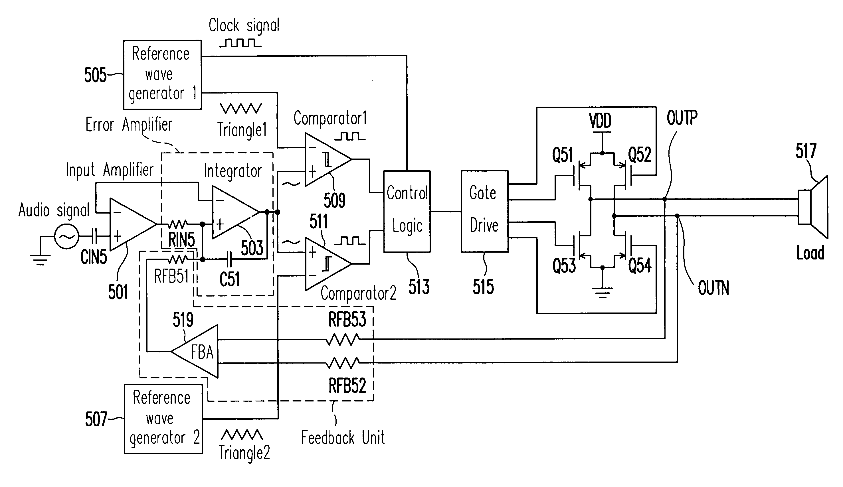
[0017]To at least achieve the above and other aspects, in one embodiment of the invention, a filterless audio power amplifier for processing an input audio signal is provided. The filterless audio power amplifier outputs differential outputs for driving a load impedance. The filterless audio power amplifier includes: an error amplifier, the input audio signal coupled to the error amplifier; first and second wave generators, generating first and second reference waves; a first comparator, responsive to the first reference wave and the input audio signal; a second comparator, responsive to the second reference wave and the input audio signal; a control logic unit, receiving outputs of the first and second comparators and further a clock signal or a reference voltage, the control logic unit resulting pulses in the differential outputs in response to the clock signal or the reference voltage and a cross relationship between the input audio signal and the first and second reference waves; a switching unit, the operation states of the switching unit being under control of the control logic unit, the switching unit outputting the differential outputs; and a feedback unit, feed backing the differential outputs to the error amplifier, the error amplifier correcting the differential outputs in response to the input audio signal. Pulses of one of the differential outputs are not overlapped with pulses of the other of the differential outputs for eliminating common mode noises of the power amplifier.
[0018]Further, in another embodiment of the invention, an audio signal processing method for driving a load impedance is provided. In the method, an input audio signal is input. Pulses in differential outputs are generated in response to a clock signal or a reference voltage and a cross relationship between the input audio signal and first and second reference waves. The differential outputs are feedback for correcting the differential outputs in response to the input audio signal. The load impedance is driven by the differential outputs. Pulses of one of the differential outputs are not overlapped with pulses of the other of the differential outputs for eliminating common mode noises.
[0019]In still another embodiment of the invention, a filterless audio power amplifier for processing an input audio signal is provided. The filterless audio power amplifier outputs a pair of differential outputs for driving a load impedance. The filterless audio power amplifier includes: an input amplifier, pre-amplifying the input audio signal; an error amplifier, receiving an output of the input amplifier; first and second reference wave generators, generating first and second reference waves; a first comparator, including a first input terminal for receiving the first reference waves, a second input terminal for receiving an output of the error amplifier and an output terminal; a second comparator, including a first input terminal for receiving the second reference waves, a second input terminal for receiving an output of the error amplifier and an output terminal; a control logic unit, receiving outputs of the first and second comparators and further a clock signal or a reference voltage, the control logic unit resulting pulses in the pair of differential outputs in response to the clock signal or the reference voltage and a cross relationship between the input audio signal and the first and second reference waves; a gate driver, coupled to the control logic unit; a switching unit, driven by the gate driver, the operation states of the switching unit being under control of the control logic unit, the switching unit outputting the differential outputs; and a feedback unit, feed backing the differential outputs to the error amplifier, the error amplifier correcting the differential outputs in response to the input audio signal. State changes of one of the differential outputs are not simultaneous with state changes of the other of the differential outputs for eliminating common mode voltages of the power amplifier.

Problems solved by technology

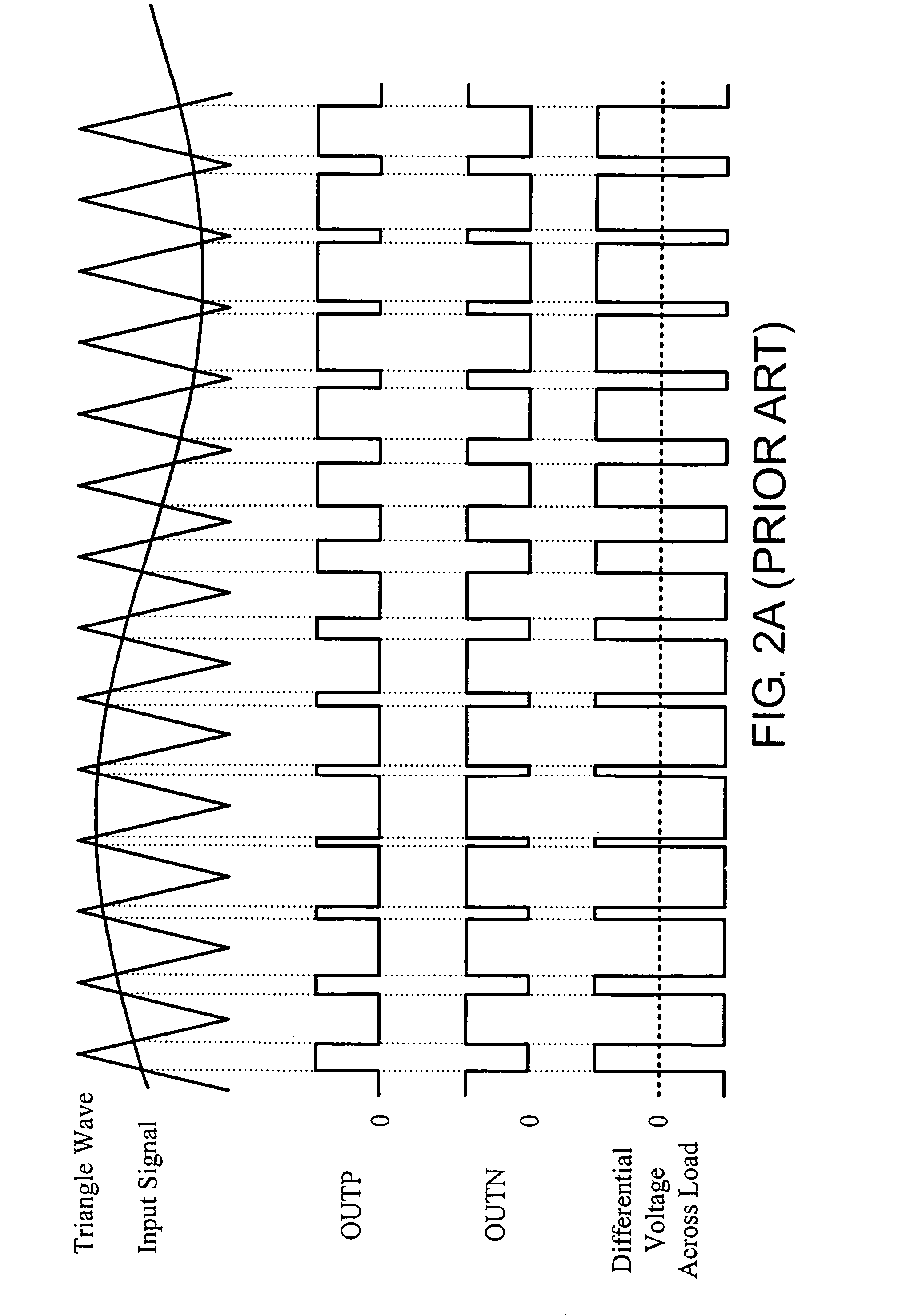
This 50% duty cycle sinks and sources large currents through the load (the speaker), resulting additional power consumption.
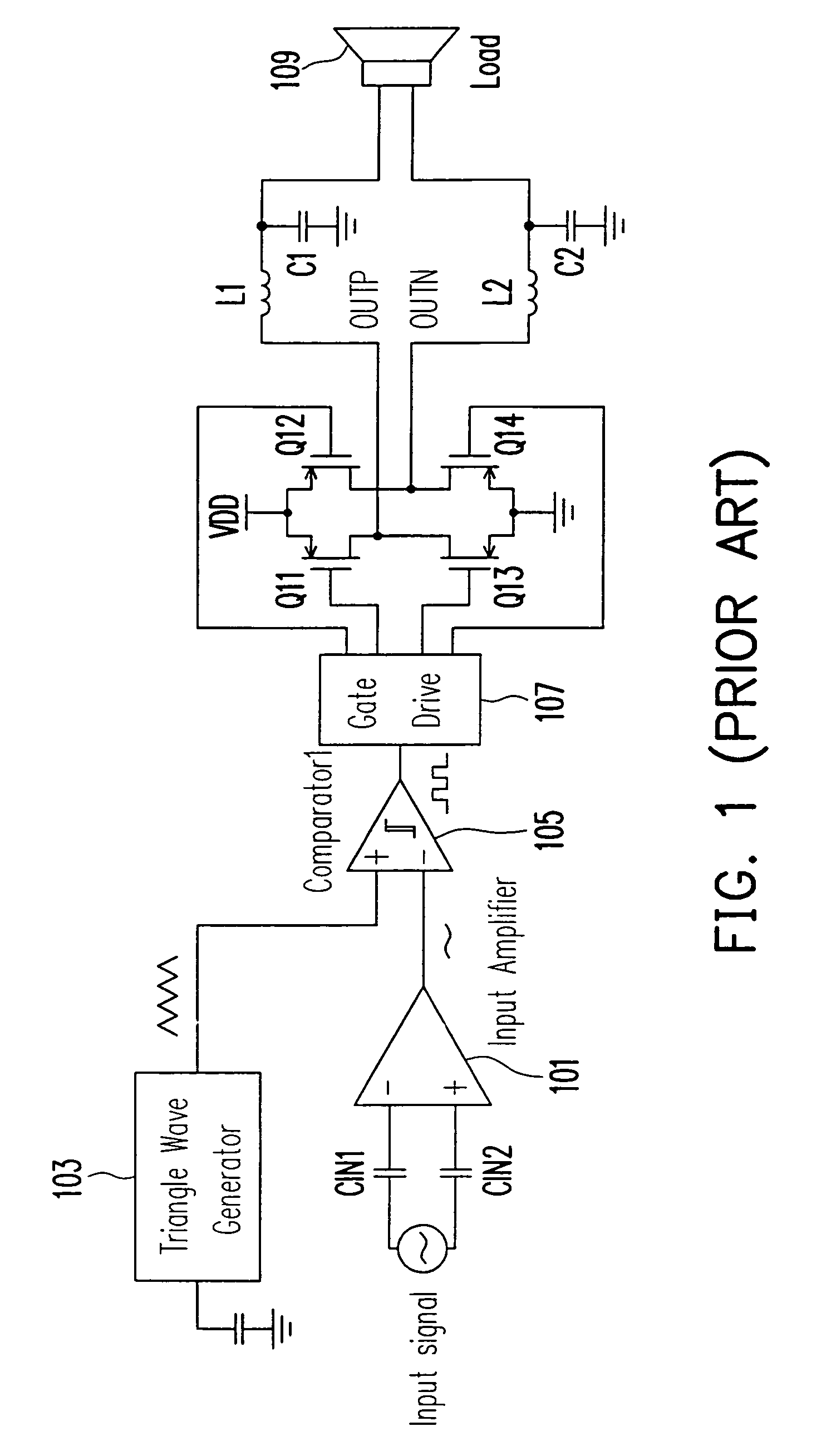
Class-D amplifiers are not popular in many portable products because the traditional class-D amplifier requires large LC filter, which increases size and solution cost.
However, this kind of modulation scheme still has a problem relying on common mode voltage variation, since OUTP and OUTN are high or low at the same time, as shown in FIGS. 4A and 4B.
The ternary modulation scheme suffers from high common mode switching noises and requires additional filter to suppress the common mode switching noises.
The common mode switching noises are more severe when the input signal is small.
Besides, this modulation scheme uses two integrators, which increases quiescent currents, circuit size and solution cost.

Method used


Image

  • Filterless class D power amplifier
  • Filterless class D power amplifier
  • Filterless class D power amplifier

Examples


Embodiment Construction

[0030]Reference will now be made in detail to the present embodiments of the invention, examples of which are illustrated in the accompanying drawings. Wherever possible, the same reference numbers are used in the drawings and the description to refer to the same or like parts.

[0031]One embodiment of the present invention provides a modulation scheme for filterless switching amplifiers with reduced EMI. The double triangular waves reduce the common mode voltage of the output signal via the two triangle waves and a control logic block added between the output of comparators and the switching unit.

[0032]FIG. 5 illustrates a diagram of a filterless class D audio power amplifier for EMI reduction according to an embodiment of the present invention. An input audio signal is input into a negative input of an input amplifier 501 via a capacitor CIN5. Input amplifier 501 pre-amplifies the input audio signal. Input amplifier 501 further has a positive input coupled to a positive input of an ...


PUM


Abstract

A double reference wave modulation scheme for filterless power amplifiers is disclosed for reducing EMI and common mode voltages. In the filterless power amplifier, differential outputs for driving load impedance are feedback and corrected based on input audio signals. Reference wave generators generate reference waves. A control logic results pulses in the pair of differential outputs in response to a clock signal or a reference voltage and a cross relationship between the input audio signal and the first and second reference waves. Pulses of one of the differential outputs are not overlapped with pulses of the other of the differential outputs for eliminating common mode noises of the power amplifier.

Description

BACKGROUND OF THE INVENTION[0001]1. Field of Invention[0002]This invention relates generally to filterless amplifiers, and more particularly, to a double reference waves filterless modulation scheme for filterless amplifiers and method thereof to reduce EMI (Electronic-Magnetic Interference) and common mode noise.[0003]2. Description of Related Art[0004]Class-D audio power amplifiers are two to five time more efficient than class-AB audio power amplifiers. Because of their greater efficiency, class-D amplifiers require smaller power supplies and eliminate heat sinks, significantly reducing overall system costs, size and weight.[0005]Class D audio power amplifiers convert audio signals into high-frequency pulses that switch the output in accordance with the audio input signal. Some class D amplifier use pulse width modulators (PWM) for generating a series of conditioning pulses that vary in width with the audio signal's amplitude. The varying-width pulses switch the power-output tran...

Claims


Application Information

Patent Timeline
Patent Type & Authority Patents(United States)
IPC IPC(8): H03F3/217H03F3/38
CPCH03F3/2173H03K7/08H03F2200/384
Inventor WU, KUO-HUNGLIU, KWANG-HWAWU, CHENG-NANCHEN, TYNG-YANG
Owner AMAZION ELECTRONICS NC
Why Eureka
Eureka Blog
Learn More