
Dual mode sample and hold circuit and cyclic pipeline analog to digital converter using the same

a cyclic pipeline and sample circuit technology, applied in the field of cyclic pipeline analog to digital converter, can solve the problems of increasing the signal to noise distortion ratio (sndr), reduce noise errors, reduce impact, and increase input common mode range

Active Publication Date: 2008-02-19
VIA TECH INC
View PDF1 Cites 10 Cited by
  • Summary
  • Abstract
  • Description
  • Claims
  • Application Information

AI Technical Summary

Benefits of technology

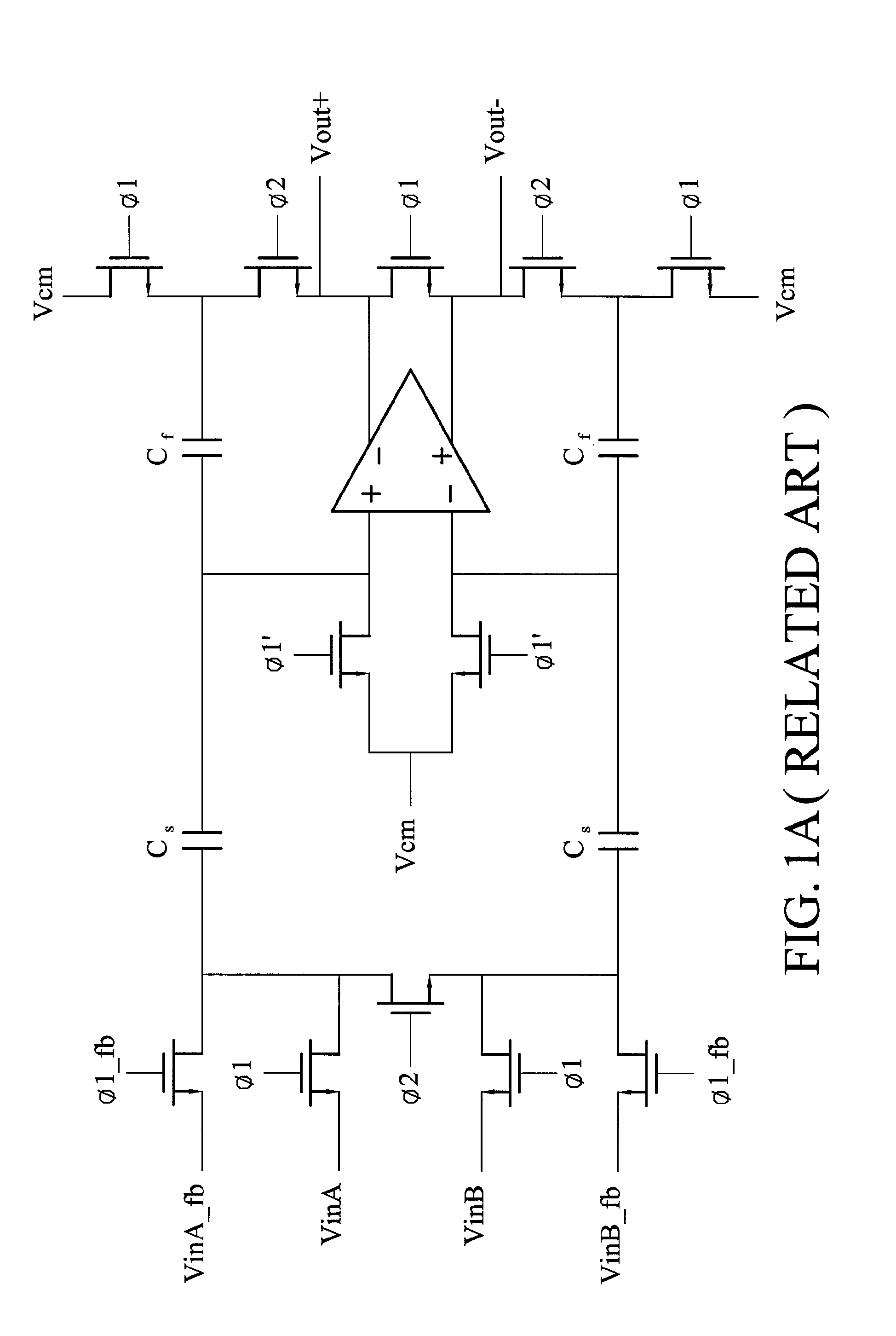
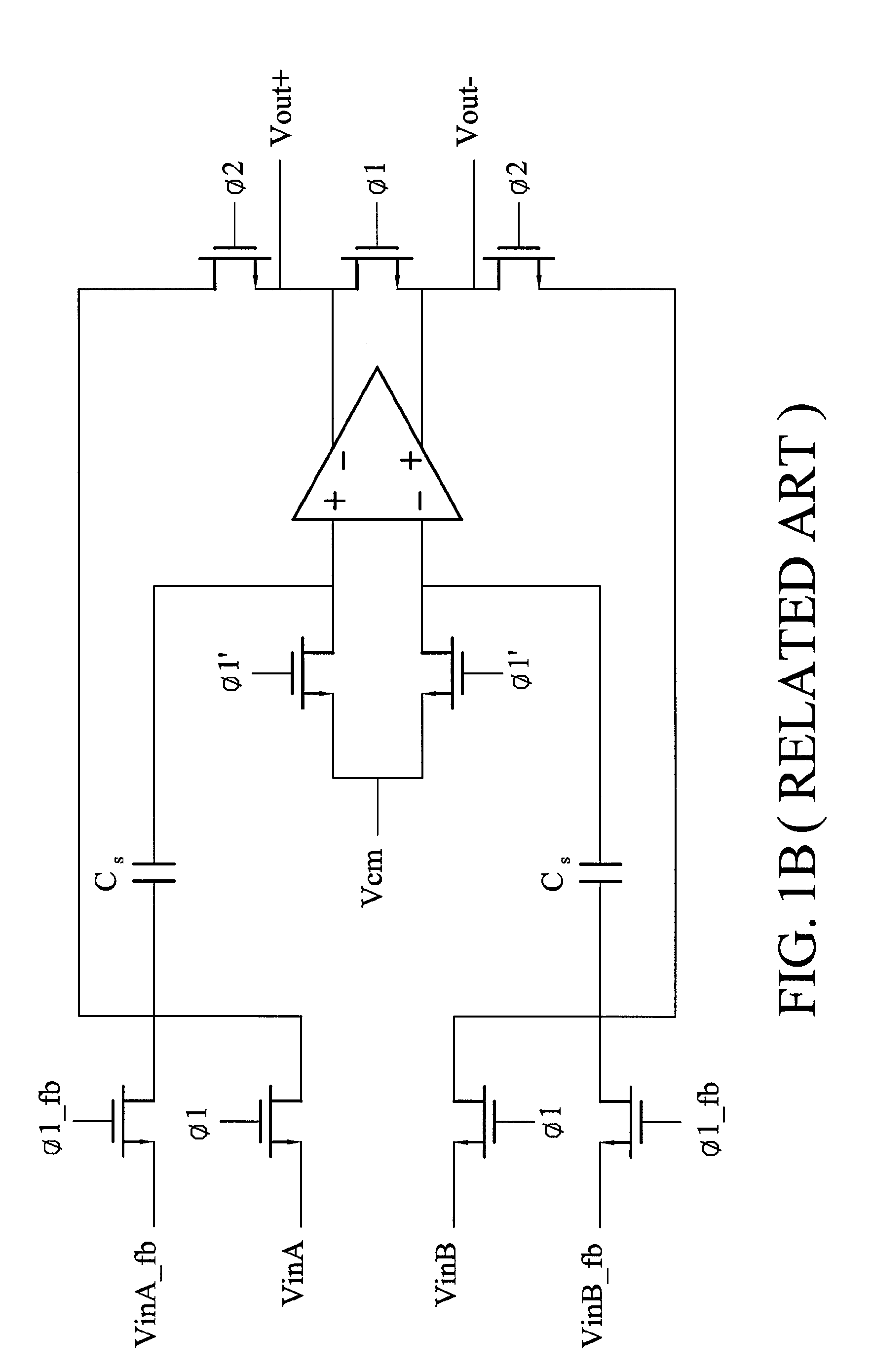
[0012]The invention combines a charge-redistribution mode and a flip-around mode in a dual mode sample and hold circuit such that input signal is not limited to single end signal only or differential signal only. Charge-redistribution increases input common mode range and reduces impact caused by common mode errors. Flip-around reduces errors caused by noises on a circuit and capacitor matching. Combination of charge-redistribution and flip-around results in better performance. Such a circuit architecture not only reduces errors of differential nonlinearity (DNL) and integral nonlinearity (INL) of a digital to analog converter but also increases signal to noise distortion ratio (SNDR).

Problems solved by technology

Such a circuit architecture not only reduces errors of differential nonlinearity (DNL) and integral nonlinearity (INL) of a digital to analog converter but also increases signal to noise distortion ratio (SNDR).

Method used


Image

  • Dual mode sample and hold circuit and cyclic pipeline analog to digital converter using the same
  • Dual mode sample and hold circuit and cyclic pipeline analog to digital converter using the same
  • Dual mode sample and hold circuit and cyclic pipeline analog to digital converter using the same

Examples


Embodiment Construction

[0020]The following description is of the best-contemplated mode of carrying out the invention. This description is made for the purpose of illustrating the general principles of the invention and should not be taken in a limiting sense. The scope of the invention is best determined by reference to the appended claims.

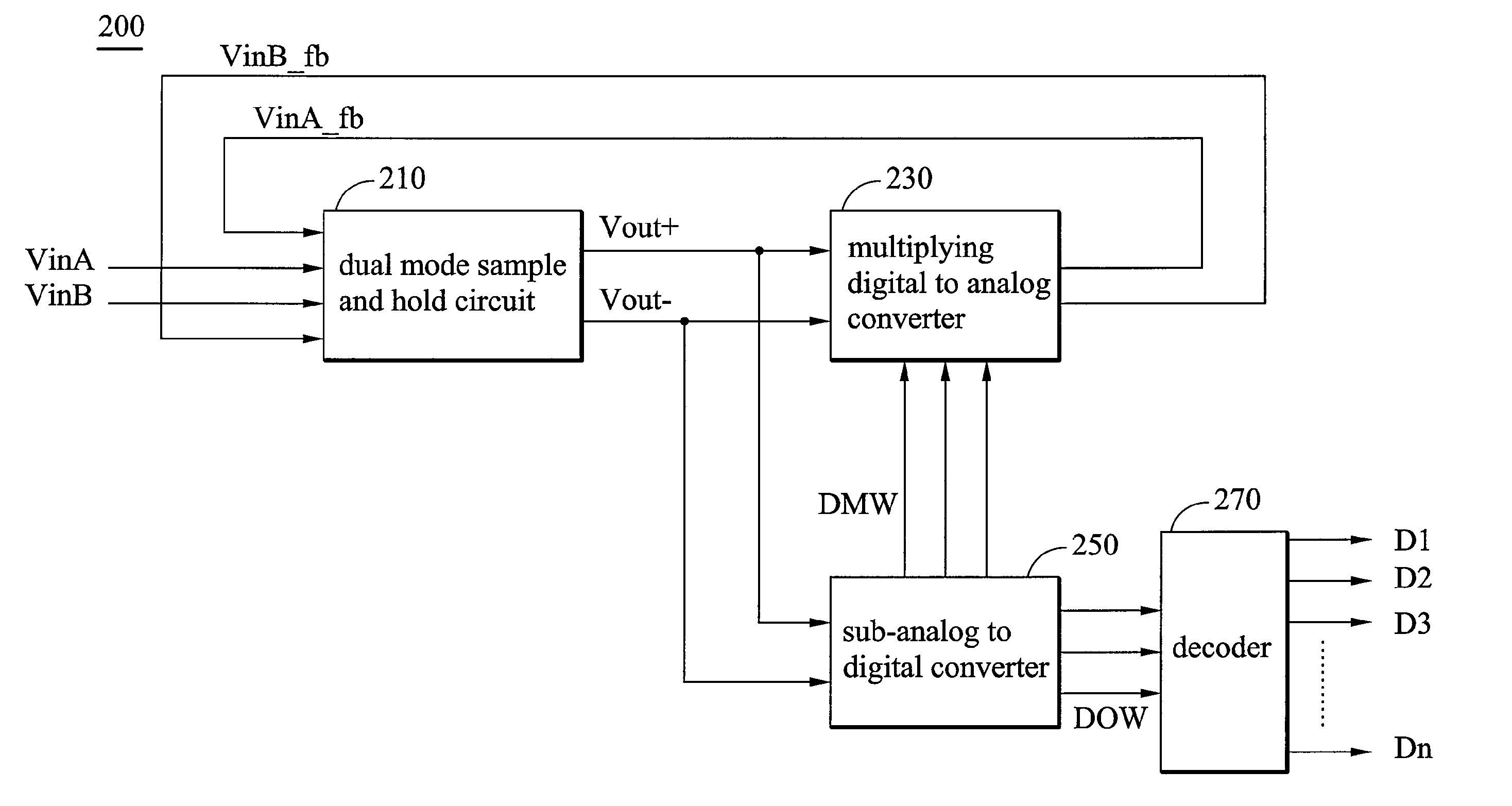
[0021]FIG. 2 is a block diagram of a cyclic pipeline analog to digital converter according to an embodiment of the invention. The cyclic pipeline analog to digital converter 200 includes dual mode sample and hold circuit 210, a multiplying digital to analog converter (MDAC) 230, a sub-analog to digital converter (sub-ADC) 250 and a decoder 270. The dual mode sample and hold circuit 210 has a charge-redistribution mode and a flip-around mode. The dual mode sample and hold circuit 210 receives first and second input voltages VinA, VinB and first and second feedback voltages VinA_fb, VinB_fb and generates a differential output signal pair Vout+, Vout−. The MDAC receives t...


PUM


Abstract

A cyclic pipeline analog to digital converter includes a dual mode sample and hold circuit, a multiplying digital to analog converter (MDAC), a sub-analog to digital converter (sub-ADC) and a decoder. The dual mode sample and hold circuit has a charge-redistribution mode and a flip-around mode. The dual mode sample and hold circuit receives first and second input voltages and first and second feedback voltages and generates a differential output signal pair. The MDAC receives the differential output signal pair and a digital multiplying word and generates the first and second feedback voltages. The sub-ADC receives the differential output signal pair and generates the digital multiplying word and a digital output word. The decoder converts the digital output word to a digital output corresponding to the first and second input voltages.

Description

BACKGROUND OF THE INVENTION[0001]1. Field of the Invention[0002]The invention relates to cyclic pipeline analog to digital conversion and, in particular, to cyclic pipeline analog to digital converters with dual mode sample and hold circuits.[0003]2. Description of the Related Art[0004]Cyclic pipeline analog to digital converters (ADC) are important in high speed circuit design. However, it is difficult to design a small-area, high-speed, and precise analog to digital circuit, especially considering inherent errors of capacitors and resistors generated during processing. Generally, tolerance of capacitance error is about 0.1%. As a result, precision of analog to digital converters is limited within 10 bits.[0005]In typical circuit architecture, single end signals are often used because of smaller area and lower power consumption. Single end signals, however, are more easily disturbed by noise. Thus, if a circuit architecture is more sensitive to noise, differential signals are often...

Claims


Application Information

Patent Timeline
Patent Type & Authority Patents(United States)
IPC IPC(8): H03M1/00
CPCH03M1/0604H03M1/0682H03M1/403
Inventor LU, WU-HUNGHSIEH, YI-BIN
Owner VIA TECH INC
Learn More