
Power supply apparatus and actuator control apparatus

Inactive Publication Date: 2008-02-19
OLYMPUS CORP
View PDF6 Cites 1 Cited by
  • Summary
  • Abstract
  • Description
  • Claims
  • Application Information

AI Technical Summary

Benefits of technology

[0013]The feature of the present invention is to provide a power supply apparatus and an actuator control apparatus which make the circuit size smaller and realize a good controllability.
[0022]According to a ninth feature of the present invention, there is provided a power supply circuit comprising: a microcontroller with the function of controlling the oscillation of a pulse signal with a specific pulse width; a DC / DC converter which uses a battery controlled by the generated pulse signal as a power supply; a regulator which converts the output of the DC / DC converter into a low voltage, wherein after a specific time has elapsed since the output of the pulse signal, the microcontroller compares the output of the regulator with the output of the DC / DC converter, thereby controlling the pulse signal.
[0023]In the present invention, the single power supply circuit generates various voltages applied to the electrodes the variable shape mirror has. A part of the power supply circuit is shared with the flash step-up power supply circuit. This makes it possible to make the circuit size smaller and improve the controllability, which is the object of the present invention.

Problems solved by technology

However, since the image formation characteristic of the plastic lens is liable to deteriorate due to a change in the temperature and humidity, use of the plastic lens requires any suitable measure to be taken against changes in the temperature and humidity.

Method used


Image

  • Power supply apparatus and actuator control apparatus
  • Power supply apparatus and actuator control apparatus
  • Power supply apparatus and actuator control apparatus

Examples


first embodiment

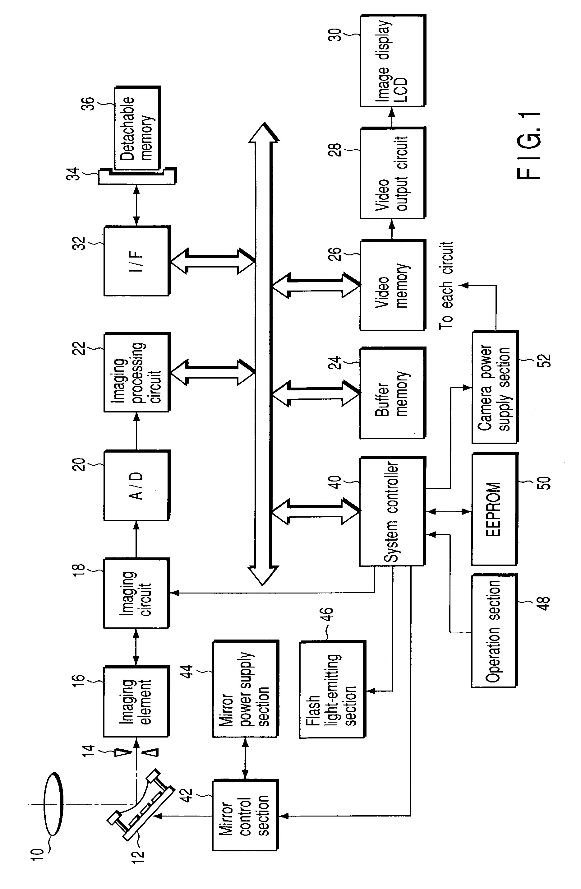
[0042]FIG. 1 shows the configuration of an electronic camera according to the present invention.

[0043]In FIG. 1, the light from a subject, or subject light, passes through an optical system 10 composed of a plurality of lenses and is reflected by the reflecting surface of an optical element having a variable shape mirror explained later, that is, a variable mirror 12. Thereafter, the amount of the subject light is controlled by a stop 14. The subject light passed through the stop 14 is caused to enter an imaging element 16, with the result that a subject image is formed on the imaging surface of the imaging element 16.

[0044]In the imaging element 16, a plurality of pixels for photoelectric conversion are arranged two-dimensionally in a matrix, thereby constituting an imaging surface. Then, a color filter is placed on the imaging surface to accumulate signal charges corresponding to the subject image formed on the imaging surface. An imaging circuit 18 is connected to the imaging ele...

second embodiment

[0072]Next, the present invention will be explained.

[0073]FIG. 6 is a conceptual diagram to help explain the principle of power supply control of the variable mirror 12 carried out in the electronic camera of the second embodiment.

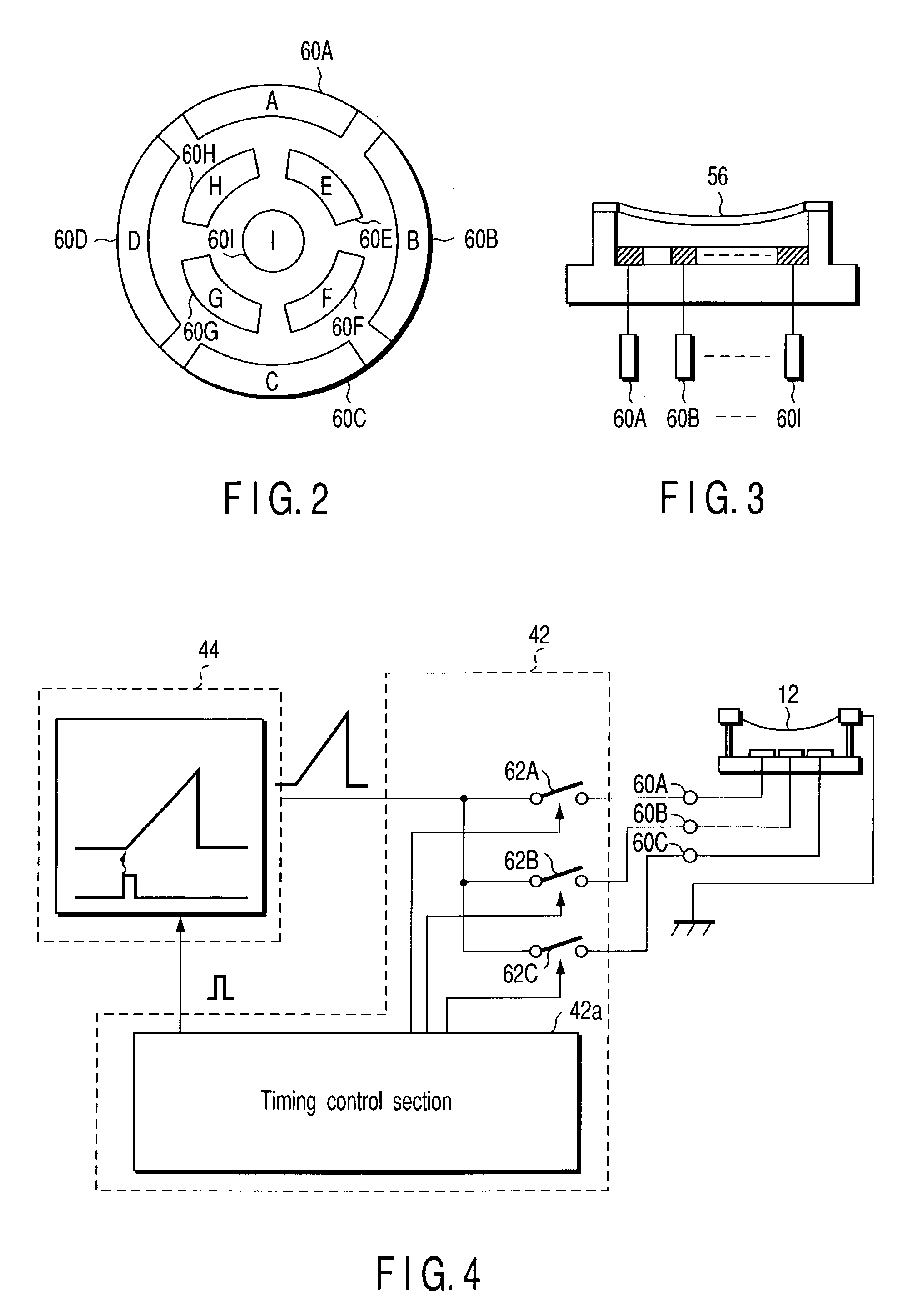
[0074]The second embodiment differs from the first embodiment in that the mirror power supply section 44 has a triangular wave power supply function of generating repeatedly a continuously and monotonously changing output voltage in place of the one-shot power supply function and that, each time the mirror power supply section 44 starts to generate the output voltage, the start timing is notified to the mirror control section 42 (trigger).

[0075]In the mirror control section 42, when the shape of the reflecting surface of the variable mirror 12 is controlled, the switches 62A to 62C are driven in synchronization with the input of a trigger from the mirror power supply section 44.

[0076]FIG. 7 is a timing chart showing an example of the operating procedure fo...

third embodiment

[0081]Next, the present invention will be explained.

[0082]An electronic camera of the third embodiment, which is obtained by improving the electronic camera of the first or second embodiment, is characterized in that the mirror power supply section 44 is configured so as to share a part of the flash light-emitting section 46.

[0083]FIG. 8 shows the configuration of the mirror power supply section 44 and flash light-emitting section 48 in the electronic camera of the third embodiment.

[0084]The flash light-emitting section 46 includes a large-capacity capacitor 46c for causing a xenon tube 46b connected to a trigger circuit 46a to emit light. To charge the large-capacity capacitor 46c, for example, a voltage as high as, for example, 330V is needed. To overcome this problem, the flash light-emitting section 46 includes a step-up power supply circuit 46d for raising the output voltage of the flash power supply much lower than 330V.

[0085]The step-up power supply circuit 46d continues to r...


PUM


Abstract

In accordance with the switching operation of a switching section, current is made to flow from a battery to an inductor repeatedly. A voltage generated at the inductor is smoothed by a condenser and then input to a regulator. A D / A converter within a CPU monitors the input to the regulator, and an output voltage of the regulator stabilizes a reference voltage of the D / A converter.

Description

CROSS-REFERENCE TO RELATED APPLICATIONS[0001]This application is based upon and claims the benefit of priority from the prior Japanese Patent Applications No. 2002-168547, filed Jun. 10, 2002; No. 2002-171626, filed Jun. 12, 2002; and No. 2002-355611, filed Dec. 6, 2002, the entire contents of all of which are incorporated herein by reference.BACKGROUND OF THE INVENTION[0002]1. Field of the Invention[0003]This invention relates to a camera which includes a power supply apparatus for applying, for example, different output voltages separately to a plurality of electrodes and a variable shape mirror with a reflecting surface whose shape varies with the output voltages applied to the electrodes. More particularly, this invention relates to a power supply apparatus and an actuator control apparatus which make the circuit size smaller and realize a good controllability.[0004]2. Description of the Related Art[0005]In recent years, so-called electronic cameras have been popularized. In ele...

Claims


Application Information

Patent Timeline
IPC IPC(8): H04N5/225G02B13/16H04N5/232
CPCH04N5/2254H04N5/232H04N23/651
Inventor NONAKA, OSAMU
Owner OLYMPUS CORP
Features
  • Generate Ideas
  • Intellectual Property
  • Life Sciences
  • Materials
  • Tech Scout
  • Unparalleled Data Quality
  • Higher Quality Content
  • 60% Fewer Hallucinations
Learn More