
System and method for securing fuel injectors

a technology for securing devices and fuel injectors, which is applied in the direction of fuel injection apparatus, charge feed systems, auxiliary lubrication, etc., can solve the problems of uneven clamping force applied to the injector(s), and cannot allow servicing of a single injector without, so as to reduce the complexity of the cylinder head, reduce the cost, weight, and assembly time, the effect of accurate rotational or radial positioning of the injectors

Inactive Publication Date: 2008-02-26
FORD GLOBAL TECH LLC
View PDF15 Cites 43 Cited by
  • Summary
  • Abstract
  • Description
  • Claims
  • Application Information

AI Technical Summary

Benefits of technology

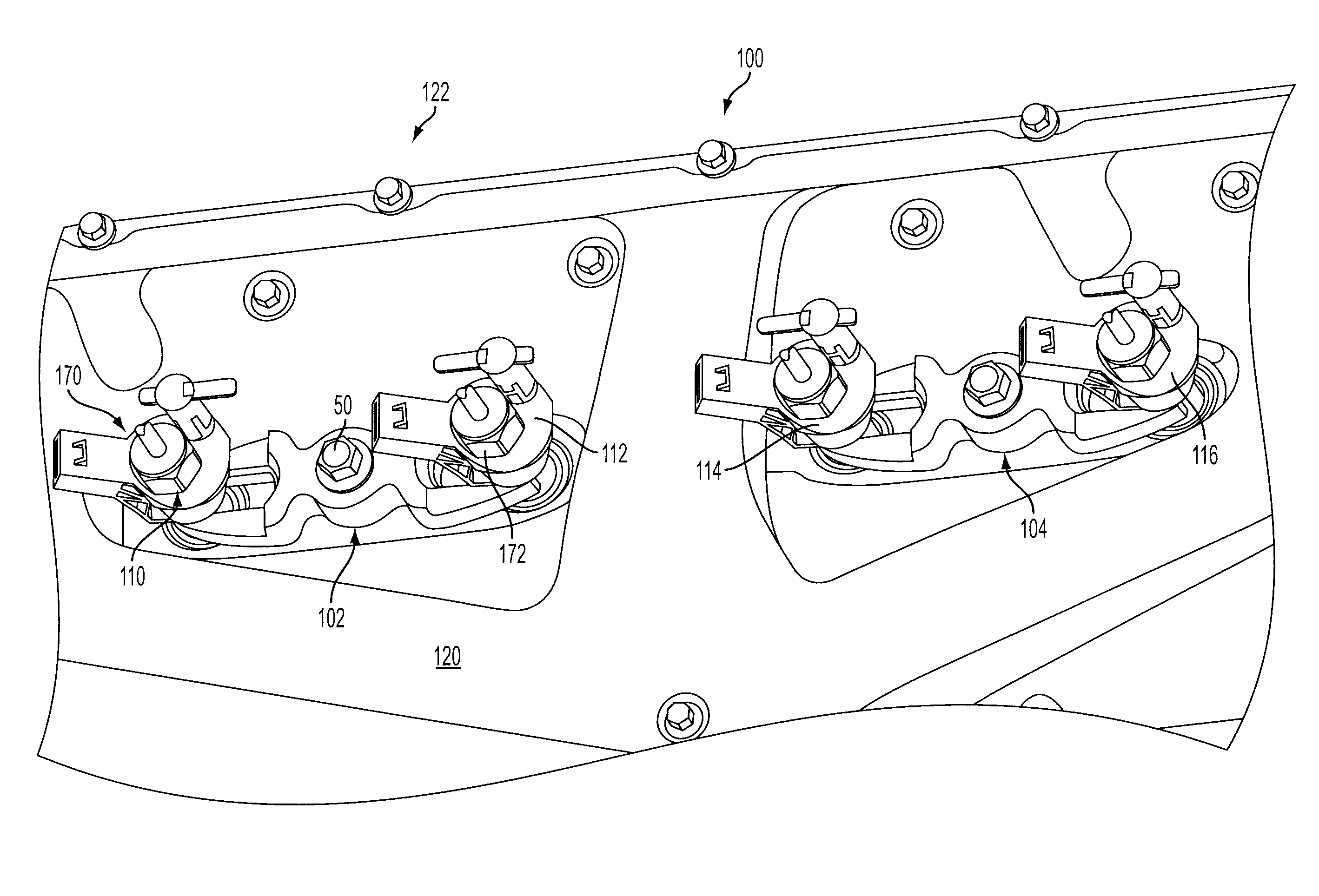
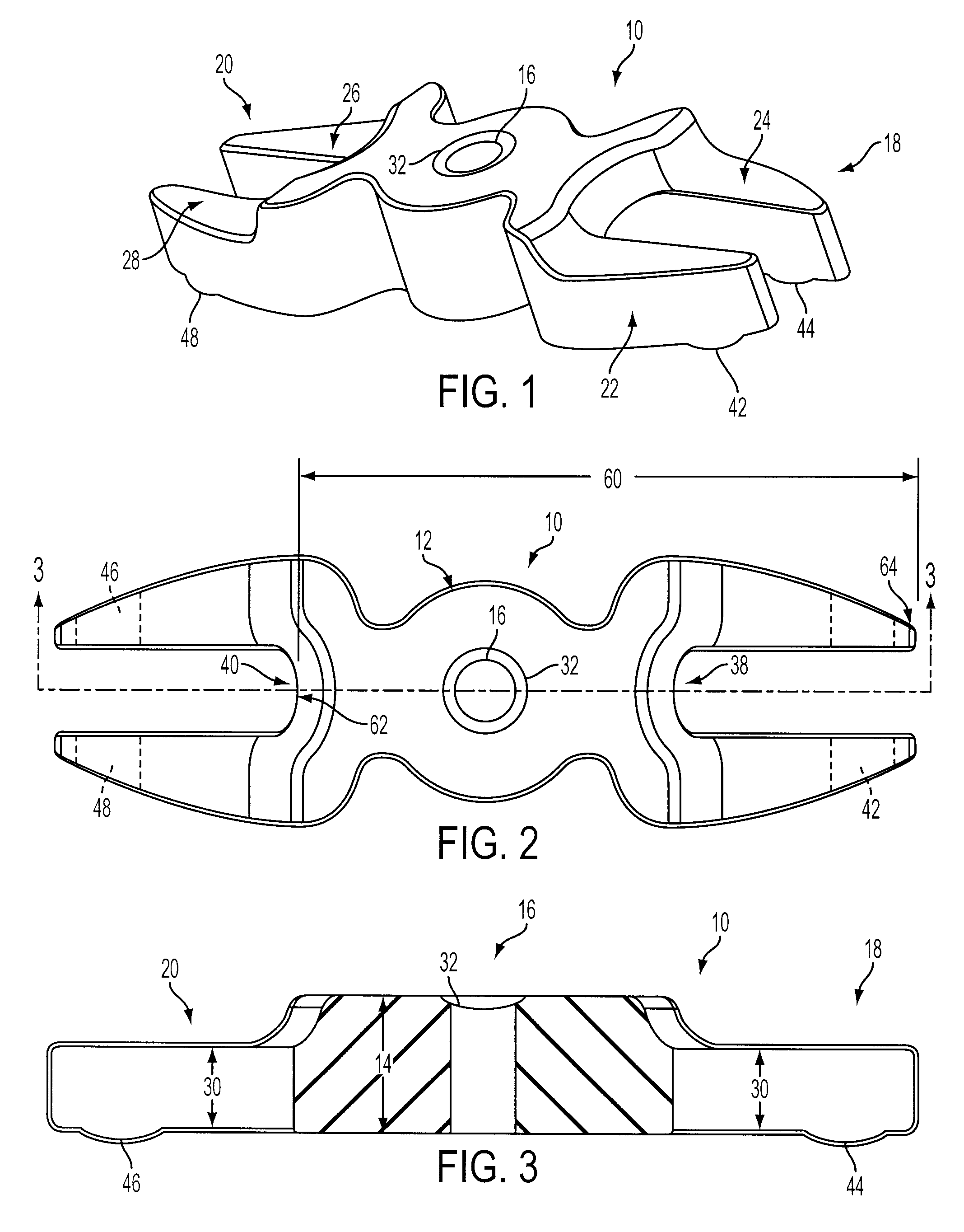
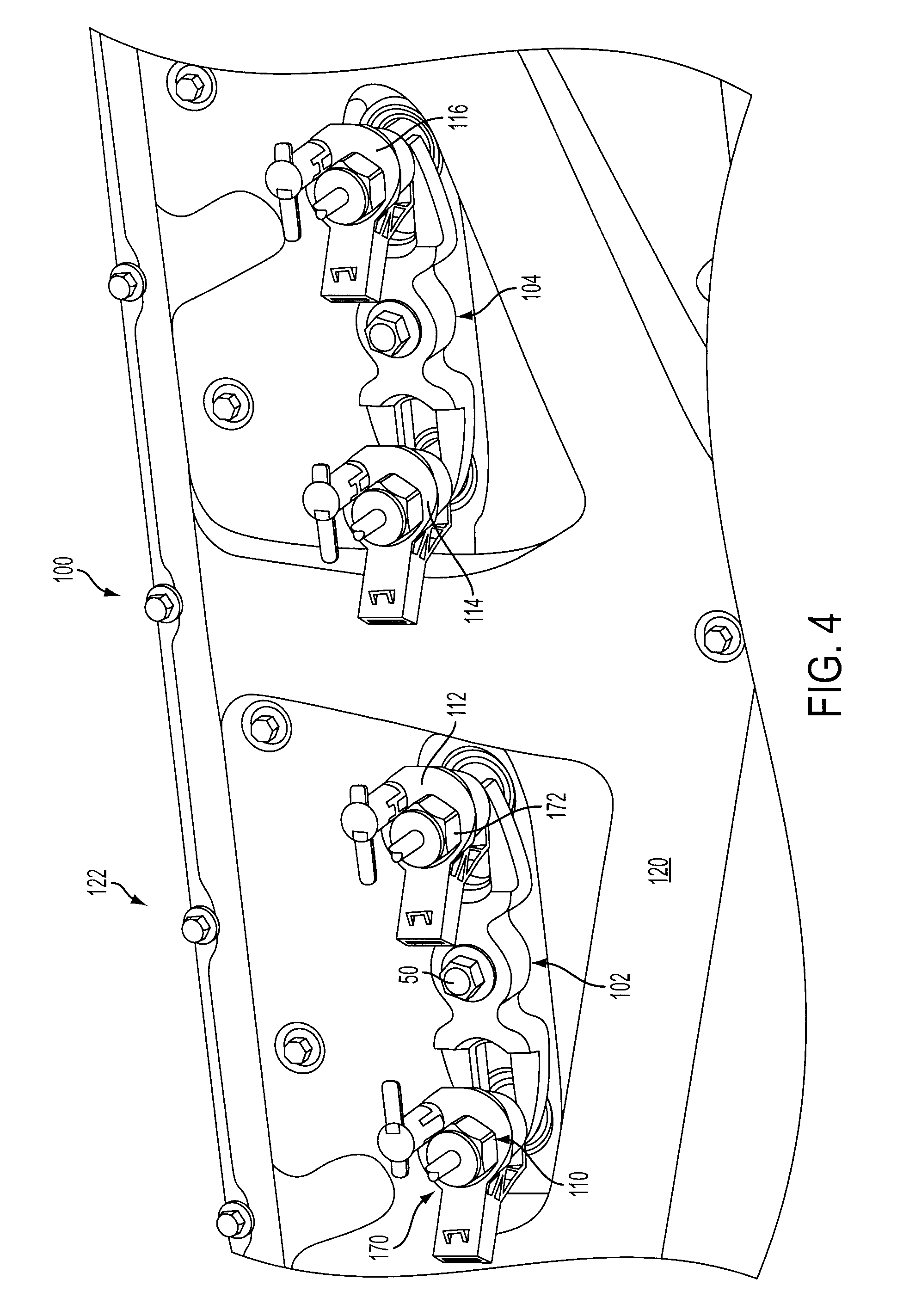
[0006]A system and method for securing fuel injectors in an internal combustion engine include a clamp for securing two adjacent injectors to a cylinder head of the engine. The clamp includes a central portion having a first thickness with a through hole having a spherical recess for receiving a fastener to secure the clamp to the cylinder head, and a pair of symmetrical crescent-shaped clamping forks each having two arms extending from a semi-circular base portion to form an arcuate U-shaped opening and having a second thickness to facilitate lateral sliding engagement with diametrically opposed flatted portions of corresponding fuel injectors to radially position or orient the fuel injectors. Each arm includes an arcuate pad or protuberance on its underside that engages a corresponding flat of the fuel injector to provide an axial downward clamping force to the fuel injector. The distance between the distal ends of one fork and the semicircular base portion of the opposite fork is selected to allow lateral sliding disengagement of the clamp from one of the associated injectors without rotation or removal of the other associated injector to facilitate servicing of individual injectors.
[0008]The present disclosure includes embodiments having various advantages. For example, the systems and methods of the present disclosure provide a single clamp to secure and orient two adjacent injectors. The fork arms of the clamp provide accurate rotational or radial positioning of the injectors in the cylinder for proper injection jet pattern alignment. The fuel injectors, injector clamps, and bolts are installed and may be serviced without removing the rocker arm cover. A single clamp and bolt secures and orients two injectors such that fewer fasteners and parts are required, which reduces cost, weight, cylinder head complexity, and assembly time. The clamping pads provide an axial clamping force that is better aligned with the injector axis and lower contact stress at the clamp / injector interface. Lateral engagement of the clamps with the injectors below the fuel and electric couplings provides more efficient packaging for various engine components, such as the cylinder head sealing rail, oil drainbacks, glow plug access, etc. The injector clamps are also designed to facilitate manufacturing using a powdered metal forming process so that no machining operations are required.

Problems solved by technology

Other designs use a single bolt to secure two adjacent injectors, but do not allow servicing of a single injector without entirely removing the clamp or, in some cases, require removing the clamp and both injectors.
Various other clamp designs use two bolts per clamp, which may result in uneven clamping forces applied to the injector(s).

Method used


Image

  • System and method for securing fuel injectors
  • System and method for securing fuel injectors
  • System and method for securing fuel injectors

Examples


Embodiment Construction

)

[0019]As those of ordinary skill in the art will understand, various features of the embodiments illustrated and described with reference to any one of the Figures may be combined with features illustrated in one or more other Figures to produce alternative embodiments that are not explicitly illustrated or described. The combinations of features illustrated provide representative embodiments for typical applications. However, various combinations and modifications of the features consistent with the teachings of the present disclosure may be desired for particular applications or implementations. The representative embodiments used in the illustrations relate generally to a four-stroke, multi-cylinder, direct-injected compression-ignition internal combustion engine. Those of ordinary skill in the art may recognize similar applications or implementations with other engine / vehicle technologies.

[0020]A representative embodiment of an injector clamp 10 for use in a system or method fo...


PUM


Abstract

A system and method for securing a fuel injector in an internal combustion engine include a clamp for securing adjacent injectors to a cylinder head. The clamp includes a central portion with a hole for receiving a fastener to secure the clamp to the cylinder head, and a pair of symmetrical crescent-shaped clamping forks forming a U-shaped opening to facilitate lateral sliding engagement with diametrically opposed flatted portions of corresponding fuel injectors. Each arm includes an arcuate pad that engages a corresponding shoulder of the fuel injector to provide an axial clamping force to the fuel injector. The distance between the distal ends of one fork and the semicircular portion of the opposite fork is selected to allow lateral sliding disengagement of the clamp from one of the adjacent injectors without rotation or removal of the other injector to facilitate servicing of individual injectors.

Description

BACKGROUND[0001]1. Technical Field[0002]The present disclosure relates to a device for orienting and securing a fuel injector for an internal combustion engine.[0003]2. Background Art[0004]Various types of holding devices or clamps have been developed for use in internal combustion engines to secure fuel injectors in corresponding cylinders of the engine. Clamps may also provide angular orientation of each injector within the cylinder to properly position the injector spray pattern relative to the piston and inlet / exhaust ports. Injector clamps satisfy various requirements that may depend upon the particular application, such as providing a sufficient force to seal the injector against the combustion pressure and providing an axial force without significant bending or torsional forces. In addition, it is desirable to minimize the number of clamps and associated fasteners to reduce part count, engine weight, and cylinder head complexity, and to simplify initial assembly operations as...

Claims


Application Information

Patent Timeline
IPC IPC(8): F02M61/14
CPCF02F7/006F02M61/14F02M2200/855
Inventor DIGGS, MATTHEWFLUHARTY, JEFFYAMBASKY, ROBERTGOOGASIAN, MARKSCHRADER, MICHAEL
Owner FORD GLOBAL TECH LLC
Learn More