Rotary impact power tool

a power tool and rotary technology, applied in the direction of power driven tools, wrenches, screwdrivers, etc., can solve the problems of irregular and inconsistent impact on the tool bi

Active Publication Date: 2008-02-26
MATSUSHITA ELECTRIC WORKS LTD
View PDF14 Cites 79 Cited by
  • Summary
  • Abstract
  • Description
  • Claims
  • Application Information

AI Technical Summary

Benefits of technology

[0004]In view of the above problem and insufficiency, the present invention has been accomplished to provide an improved rotary impact power tool which is capable of generating regular and consistent impact even when the drive shaft is rotating at a low speed. The impact power tool in accordance with the present invention includes a motor rotating a drive shaft, an output shaft configured to hold a tool bit, and a hammer coupled to the drive shaft. The hammer is rotatable together with the drive shaft and is engageable with an anvil fixed to the output shaft so as to give a rotary impact to the output shaft as the drive shaft rotates. The tool further includes a trigger which is manipulated by a user to determine a speed index indicative of an intended speed of the drive shaft in proportion to a manipulation amount, a speed commander configured to generate a target speed based upon the speed index, and a speed detector configured to detect a rotation speed of the drive shaft to give a detected speed. Also included in the tool is a speed controller which generates a control signal for driving the motor in order to match the detected speed with the target speed. The speed controller is configured to set a detection time frame, and to adopt a predefined pseudo-detection speed as a substitute for the detected speed when the speed controller receives no detected speed from the speed detector within the detection time frame. The pseudo-detection speed is a minimum speed greater than zero and varies in accordance with the target speed. Accordingly, even if no speed detection continues, i.e., the motor is stalled over the detection time frame, the speed controller can successfully generate the control signal by making the use of the pseudo-detection speed, thereby continuing to rotate the drive shaft for generating the impact regularly and consistently without causing a delay.
[0005]Preferably, the detection time frame is set as a function of the speed command. Thus, the tool can give the above effect over a wide range of the rotation speed of the drive shaft or motor, thereby enabling to generate the impact cyclically in accordance with the rotation speed designated by the speed command.
[0006]The power tool is preferred to include a load detector for detection of an amount of load acting on the drive shaft. In this connection, the speed controller may be configured to have different control modes which rely respectively upon different speed-control parameters for determination of the control signal. The speed controller selects one of the different control modes based upon the detected load. Thus, the tool is enabled to improve a response for generating the control signal irrespectively of the amount of the load, thereby keeping the regular impact especially when the rotation speed is relatively low under a heavy load condition.
[0007]The speed controller may be configured to check whether or not the control signal designates the rotation speed lower than a predetermined minimum speed, and to modify the control signal to designate the minimum speed, in case when the control signal designates the rotation speed lower than the minimum speed. Accordingly, even when the drive shaft is rotating at a relatively low speed, the speed controller can give a sufficient force of rotating the drive shaft immediately after the impact is given to the output shaft, thereby assuring to keep the hammer rotating for generating the impact sufficiently and consistently without a delay.
[0008]Further, the speed controller may be configured to update the control signal every predetermined cycle while obtaining a speed difference in the rotation speed designated by the control signals between the current and previous cycles, and to limit the speed difference within a predetermined range. Thus, it is enabled to restrain over-response of varying the rotation speed of the drive shaft, thereby assuring to give a stable and consistent impact motion, especially at a relatively low speed where a relatively large speed difference occurs between immediately before and after the impact is generated.

Problems solved by technology

With this consequence, the speed controller is unable to generate a proper speed command until the drive shaft starts rotating, thereby causing a response delay and even the temporary stalling of the motor, which would result in irregular and inconsistent impact on the tool bit.

Method used


Image

  • Rotary impact power tool
  • Rotary impact power tool
  • Rotary impact power tool

Examples


Embodiment Construction

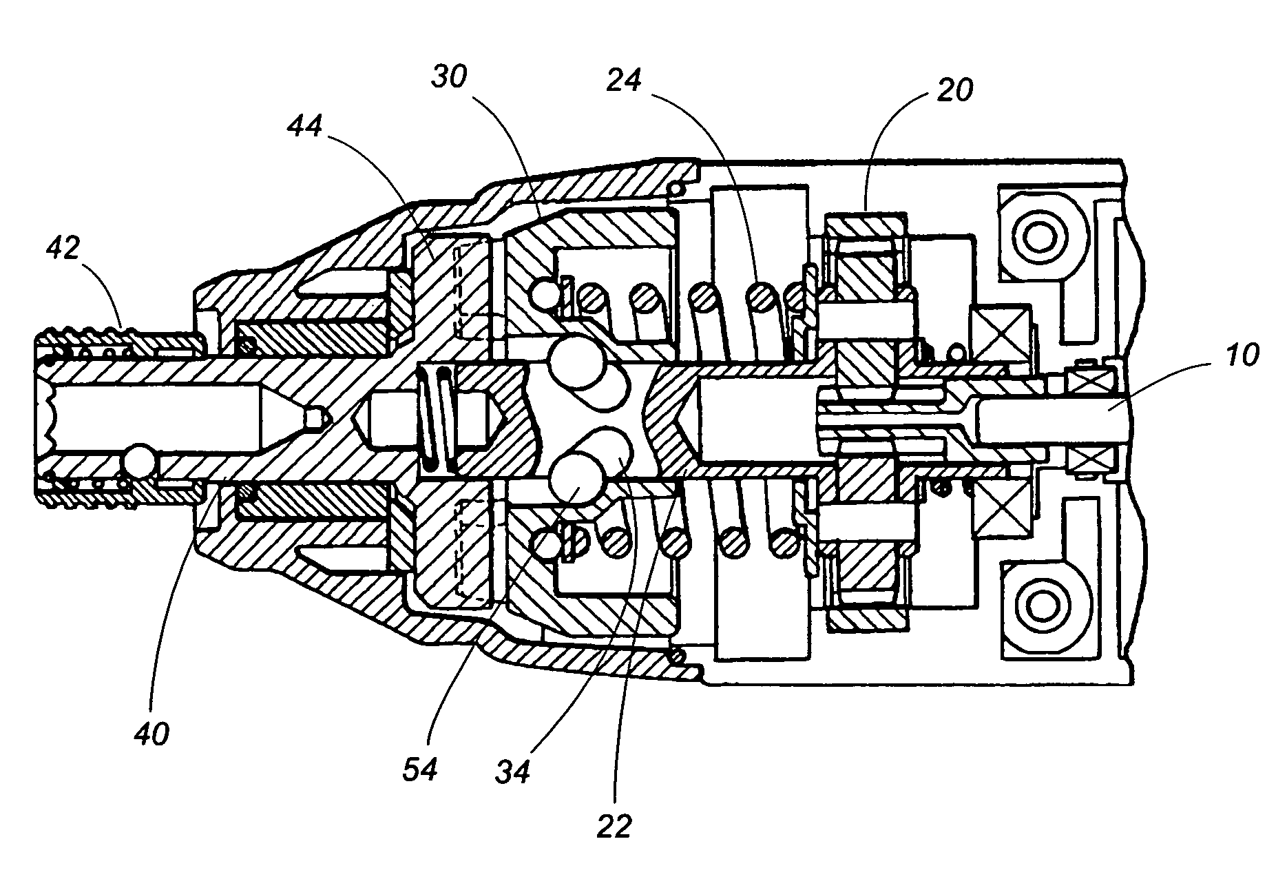
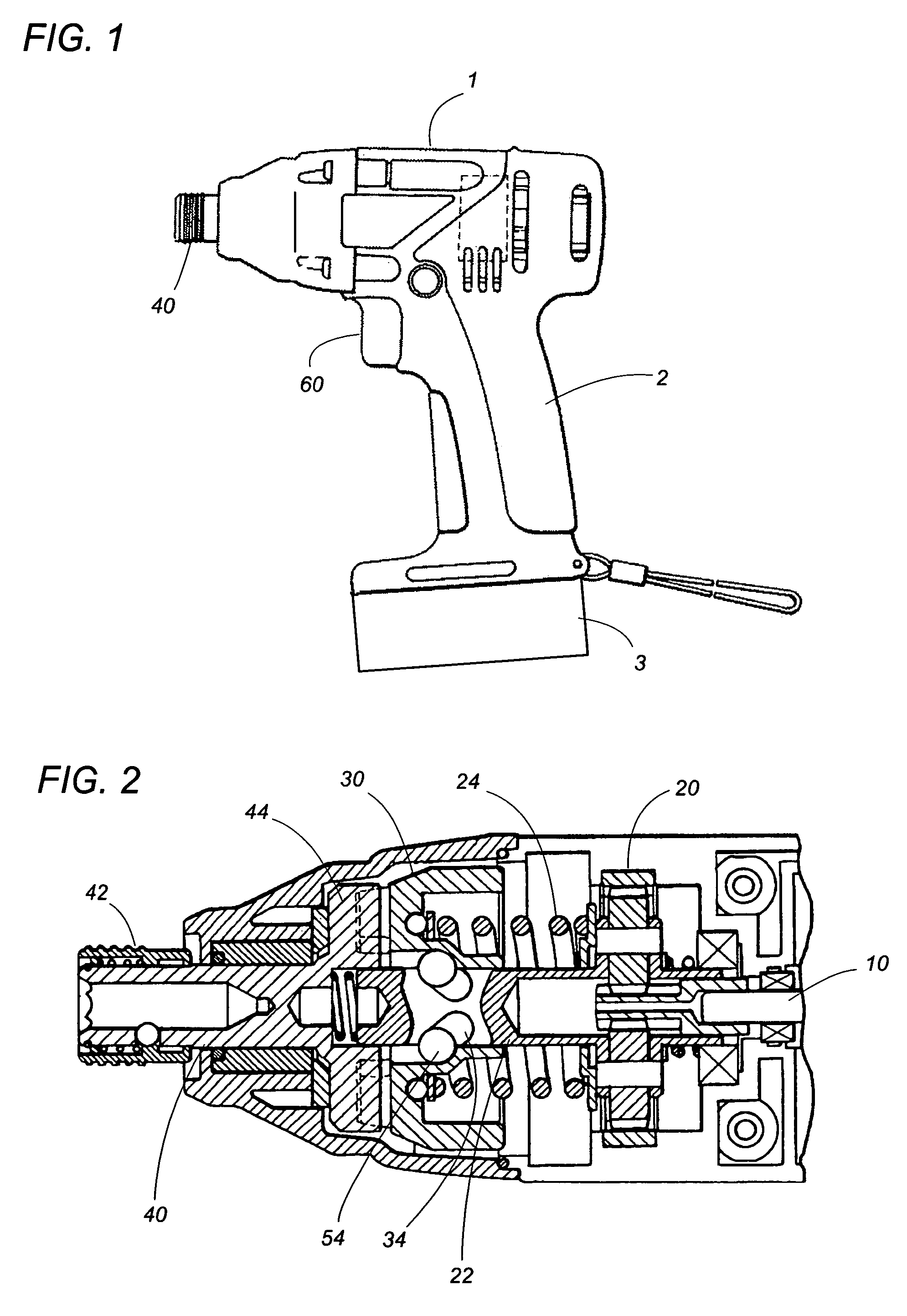
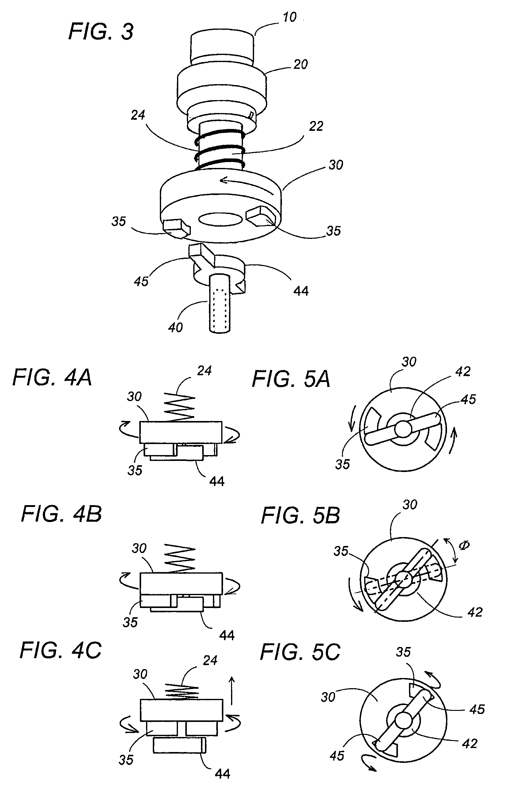
[0024]Referring now to FIGS. 1 to 3, there is shown a rotary impact power tool in accordance with a preferred embodiment of the present invention. The power tool has a casing with a main body 1 and a hand grip 2. The main body 1 accommodates therein an impact drive unit composed of a brushless three-phase motor 10, a reduction gear 20 with a drive shaft 22, and an output shaft 40 adapted to hold a tool bit (not shown) such as a screwdriver, drill, or wrench bit. The output shaft 40 is held rotatable within the front end of the main body 1 and carries at its front end a chuck 42 for mounting the tool bit. The motor 10 has a rotor carrying permanent magnets and a stator composed of three-phase windings. The rotor is connected to the reduction gear 20 to rotate the drive shaft 22 at a reduced speed. A battery pack 3 is detachably connected to the lower end of the hand grip 2 to supply an electric power to the motor 10.

[0025]A hammer 30 is coupled at the front end of the drive shaft 22 ...


PUM


Abstract

A impact power tool includes a motor rotating a drive shaft, an output shaft holding a tool bit, and a hammer coupled to the drive shaft. The hammer is rotatable together with the drive shaft and is engageable with an anvil fixed to the output shaft so as to give a rotary impact to the output shaft. The tool includes a speed commander generating a target speed intended by a user, and a speed detector for detection of a speed of the drive shaft. A speed controller generates a control signal for driving the motor by referring to the target speed and the detected speed. The speed controller provides a detection time frame, and to adopt a predefined pseudo-detection speed as a substitute for the detected speed when no speed detection is available within the detection time frame. Accordingly, even if no speed detection continues, i.e., the motor is stalled over the detection time frame, the speed controller can successfully generate the control signal by making the use of the pseudo-detection speed, thereby continuing to rotate the drive shaft for generating the impact regularly and consistently without causing a delay.

Description

TECHNICAL FIELD[0001]The present invention is directed to a rotary impact power tool such as an impact screwdriver, wrench or drill.BACKGROUND ART[0002]Impact tools have been widely utilized to facilitate drilling and tightening of screws or nuts with the aid of an impact. Japanese Patent Publication JP2005-137134 discloses a typical impact tool which is designed to vary a rotation speed in accordance with a manipulation amount of a trigger button. The impact tool has a motor driving a drive shaft carrying a hammer, and an output shaft holding a tool bit. The hammer is engageable with an anvil fixed to the output shaft in order to give a rotary impact to the output shaft, i.e., the tool bit. The tool includes a speed commander which, in response to the manipulation amount of the trigger button, a speed command designating a rotation speed at which the drive shaft is rotated. Also included in the tool is a speed controller which generates a control signal for rotating the driving sha...

Claims


Application Information

Patent Timeline
Patent Type & Authority Patents(United States)
IPC IPC(8): B25B21/02
CPCB25B21/02B25B23/1405B25B23/1475
Inventor ARIMURA, TADASHI
Owner MATSUSHITA ELECTRIC WORKS LTD
Why Eureka
Try Eureka