Each of these competing technologies has pros and
cons: (1) for a given screen
diagonal, PDP and LCD displays are generally more expensive than Rear Projection displays; (2) PDP and LCD displays generally are much thinner than Rear Projection displays; (3) although PDP and LCD displays are generally thin enough to
mount on a wall, such displays tend to be heavy enough that mounting on a wall can be difficult; (4) Rear Projection displays are typically more cost-effective than PDP and LCD displays; and (5) Rear Projection displays do not offer a low-profile form-factor, as a result may occupy too much space in a room, often making a Rear
Projection display not being the display of choice as a
large screen display.
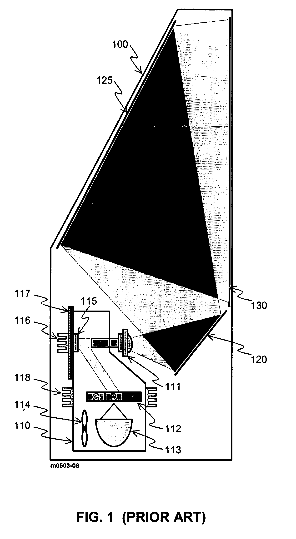
When combined with the efficiency of the light source lamp 113 itself, the poor luminance efficiency of rear
projection display devices contribute to creating a thermal management problem that typically requires at least one cooling fan 114 and an additional cooling fin 11.
The addition of a fresnel component to the screen 130 adds cost and makes the brightness of the screen vary with the viewing angle.
In addition to having a typically poor efficiency, the high-pressure arc lamps typically used as a light source lamp 113 needed to generate sufficient luminance for large screen projection also have very poor lifetime and reliability.
Such poor reliability when combined with the inherently poor reliability of the motor driven
color wheel and cooling fan makes the overall reliability of large screen rear projection devices of FIG. 1 even worse.
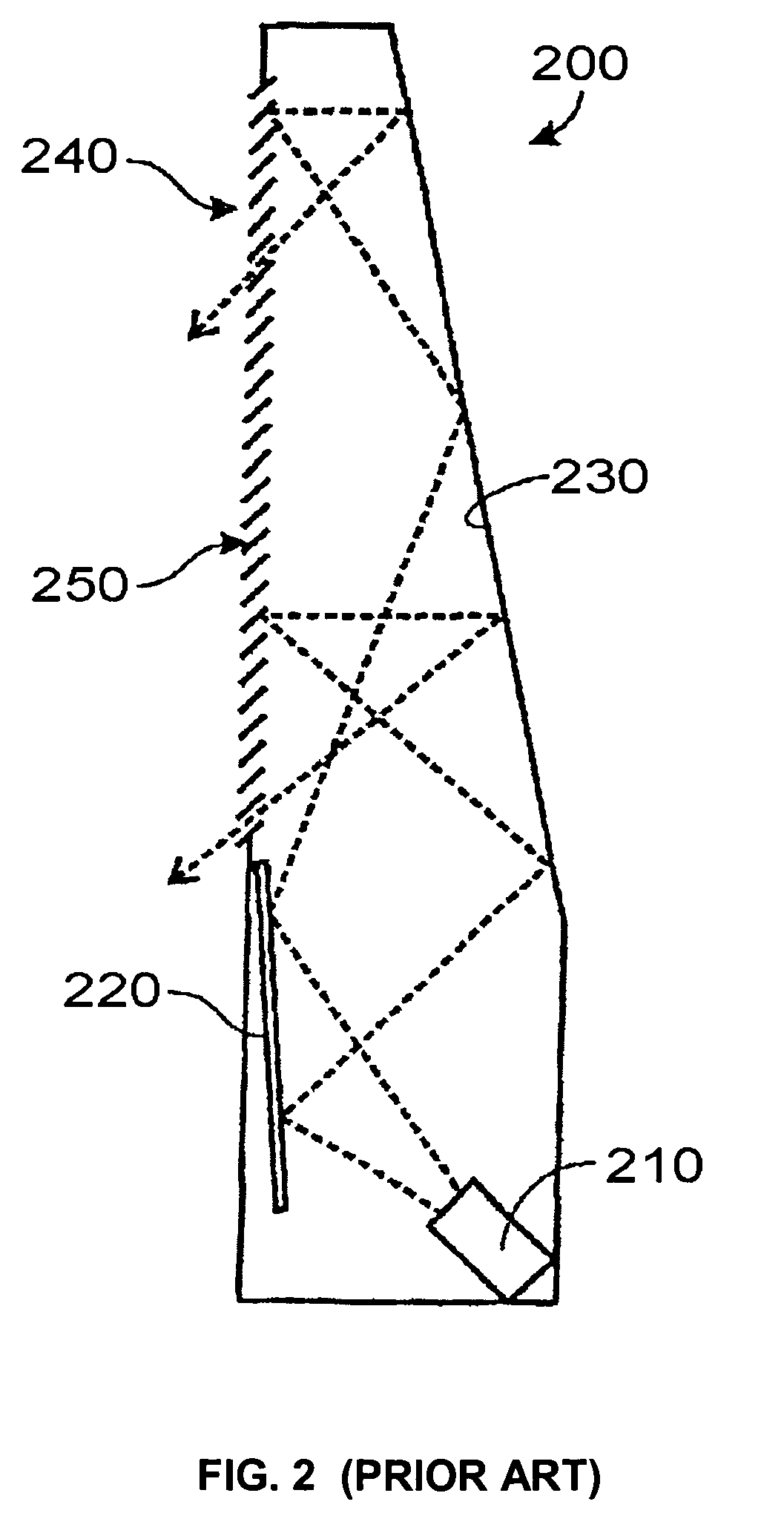
However, such thinner rear projection display devices typically rely on the use of aspherical mirrors, which are difficult to manufacture and difficult to align, which results in the display becoming expensive (see U.S. Pat. Nos. 6,485,145, 6,457,834, 6,715,886 and 6,751,019). FIG. 2 illustrates another prior art thin rear projection
display device 200 that overcomes the use of aspherical mirrors (see U.S. Pat. Nos. 6,728,032 and 6,804,055 and U.S.
Patent Application Publication No. 2004 / 0032653).
The former technique tends to make the
projection optics quite expensive while the latter technique tends to substantially increase the height needed under the screen area.
Furthermore, the multiple
light cone folding employed tends to severely complicate the
light cone alignment, making the rear projection
display device difficult to manufacture, thus more costly.
In addition, the use of exotic fresnel designs combined with the use of multiple
light cone folding tend to further degrade the luminance efficiency of the display device, thus making it have poor brightness performance.
Further, the thin rear projection display device 200 of FIG. 2 suffers from the same poor reliability performance as that of the rear projection display device 100 illustrated in FIG. 1.
Although the primary motive of doing so would be to get rid of the inefficiencies, thermal management and reliability problems associated with the high-pressure
arc lamp and the
color wheel, in the prior art projection display device 300 the LED devices are placed in a relatively close vicinity, thus causing thermal management to reemerge as a problem that requires careful consideration, especially when LED devices performance degrades considerably when their
junction temperature rises excessively.
Furthermore, the prior art projection display device 300 attempts to use the
LED array 310 to literally replace the high-pressure
arc lamp as a light source in terms of its aperture and luminance output by using a
complex system comprised of the
LED array 310, array cover plate 315,
optical fiber bundle 340, optical
integrator 350, and
optical path lens group 360, making the light source
assembly quite cumbersome and complex to integrate, thus resulting in a complex and costly display device.
In addition, the prior art projection display device 300 does not include any provisions to compensate for the fact that LED devices are nearly impossible to maintain a fixed color-point, because the performance of red, green and blue LED devices degrades at different rates and their color shifts with age and as the temperature changes.
Furthermore, the prior art projection display device 300 does not include any provisions for sensing and controlling the color and brightness output of the LED devices, which is critical for maintaining a fixed color-
point projection output.
Because of the aforementioned weaknesses, the approach for using LED devices as a light source used in the prior art projection display device 300 would not be viable for use in large screen size rear projection display devices.
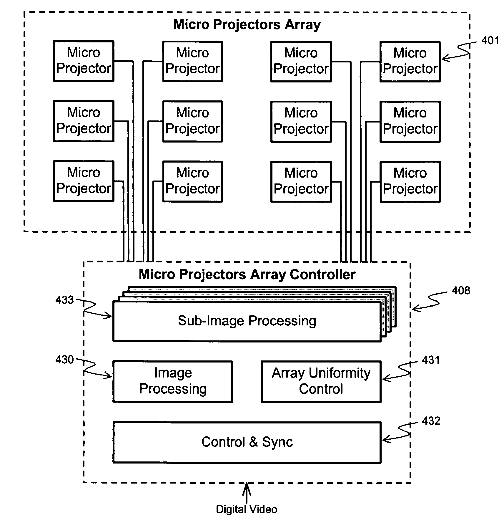
Although U.S. Pat. Nos. 4,974,073, 5,136,390, 6,115,022, 6,254,239 and 6,760,075 describe methods for seamless tiling of multiple projectors, these methods fail to address the critical issue of maintaining chromatic and luminance uniformity across the multiple projectors used.
In effect the method described in U.S. Pat. No. 6,568,816 would attain a degree of chromatic and luminance uniformity across the multiple projectors at the expense of severely degrading the luminance efficiency due to light lose in the splitters.
In general, the apparatus and methods described in U.S. Pat. Nos. 4,974,073, 5,136,390, 6,115,022, 6,254,239, 6,568,816 and 6,760,075 would be suitable for large venue wall displays and their
resultant implementation are bulky and as such are not suitable for building
consumer desired size and form factor large screen rear projection display devices.
In
spite of the numerous existing prior art that pertains to displays that create an image by tiling its segments, none was found that describes an integrated,
consumer desired size & form factor large screen (50″ or larger screen diagonal) rear projection display device that generates a seamless composite image that is created by tiling its constituent sub-image segments.

