Digital camera with sensitivity compensation

a digital camera and sensitivity compensation technology, applied in the field of digital cameras, can solve problems such as image deterioration, obvious color shifting, image deterioration, etc., and achieve the effect of effective compensation

Inactive Publication Date: 2008-02-26
FUJIFILM CORP
View PDF16 Cites 9 Cited by
  • Summary
  • Abstract
  • Description
  • Claims
  • Application Information

AI Technical Summary

Benefits of technology

[0022]According to the third aspect of the present invention, the correction is not carried out when the mechanical shutter is used, and when the electronic shutter is used, the sensitivity correction is carried out. Thus, the gain compensation can be implemented effectively.

Problems solved by technology

In these interline-type CCD sensors, in a case in which a shutter speed of the electronic shutter is fast, a difference between exposure times of the odd field and the even field occurs at the time of reading out the accumulated charges, which leads to image deterioration, such as the occurrence of flicker and the like.
Consequently, obvious color shifting may occur, and image deterioration may result (see FIG. 6).

Method used


Image

  • Digital camera with sensitivity compensation
  • Digital camera with sensitivity compensation
  • Digital camera with sensitivity compensation

Examples


Embodiment Construction

[0029]Herebelow, an embodiment of the present invention is described in detail with reference to the drawings.

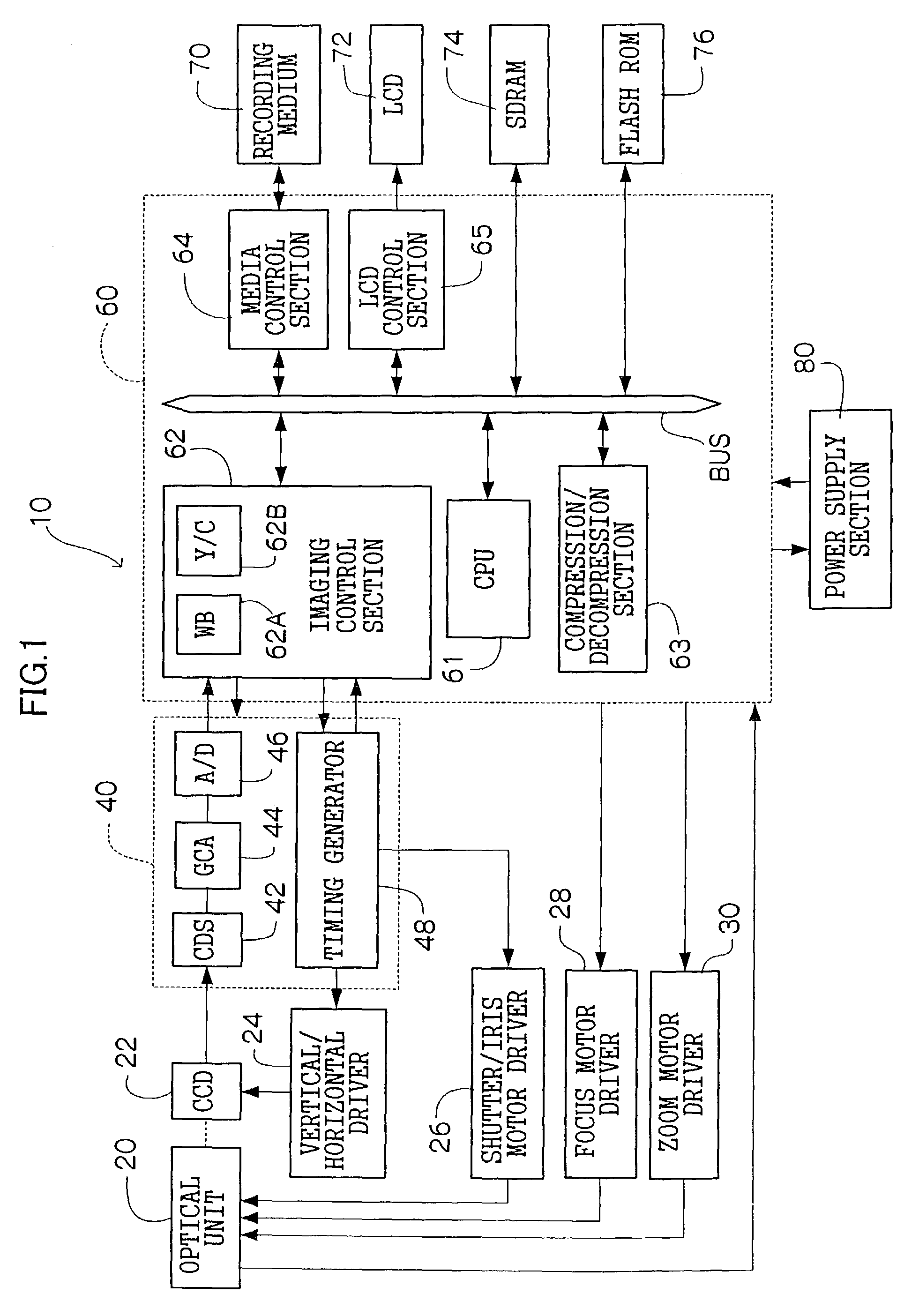
[0030]FIG. 1 shows a schematic structural diagram of a digital camera 10 relating to the present embodiment. The digital camera 10 has a structure which includes an optical unit 20, a CCD 22, a signal-processing section 40, a main control section 60, a vertical / horizontal driver 24, a shutter / iris motor driver 26, a focus motor driver 28, and a zoom motor driver 30. The optical unit 20 has a structure including a lens for focusing a subject image. The CCD 22 is disposed at a rear side of the lens, on an optical axis thereof. The signal-processing section 40 creates digital image data which represents the subject image on the basis of output signals from the CCD 22, and generates timing signals for driving each section of the optical unit 20, the CCD 22 and the like. The main control section 60 administers overall operations of the digital camera 10. The vertical / horizontal d...


PUM


Abstract

Voltage signals outputted from a CCD are subjected to correlated double sampling processing by a correlated double sampling circuit (CDS), after which digital gain processing is carried out at a gain control amplifier (GCA). A gain difference between G color signals and R/B color signals outputted from the CCD is caused by a difference between a G exposure duration tG and an R/B exposure duration tR/B. When the value of a ratio between the tG and the tR/B falls below a predetermined value, the GCA applies digital gain for compensating for the gain difference by multiplying respective signal values of R, G and B by gain correction coefficients as follows: (gain compensation coefficient α)=(G exposure duration tG)/(R/B exposure duration tR/B)=(G exposure duration tG)/((G exposure duration tG)+(exposure duration difference Δt)).

Description

BACKGROUND OF THE INVENTION[0001]1. Field of the Invention[0002]The present invention relates to a digital camera, and particularly to a digital camera equipped at least with a high-speed electronic shutter.[0003]2. Description of the Related Art[0004]In recent years, digital cameras which take still pictures or moving pictures of image subjects by utilizing a solid state imaging system, whose structure includes a solid-state imaging element such as a CCD (charge coupled device) sensor or the like for photographing a subject, have become common.[0005]“Interline transfer-type CCD sensors” (referred to simply as “CCD sensors” below) are often employed in such digital cameras. An interline transfer-type CCD sensor is provided with photodiode (PD) sections, a plurality of vertical transfer registers, a horizontal transfer register, transfer gates (TG), and an overflow drain (OFD). The PD sections serve as solid-state imaging elements, which are, for example, rectangularly disposed at re...

Claims


Application Information

Patent Timeline
Patent Type & Authority Patents(United States)
IPC IPC(8): H04N5/335H04N5/235H04N5/243H04N5/353H04N5/365H04N5/369H04N5/3728H04N5/378H04N9/07H04N101/00
CPCH04N5/2353H04N5/243H04N9/045H04N23/673H04N23/73H04N23/76H04N23/84
Inventor KUBO, NAOKI
Owner FUJIFILM CORP
Why Eureka
Try Eureka