Configuring a data transmission interface in a communication network

a data transmission interface and communication network technology, applied in data switching networks, instruments, frequency-division multiplexes, etc., can solve the problems of data transport via the iub interface, delays and delay variations, and delays that cannot be altered any more, so as to increase the delay, maintain the transmission quality, and increase the statistical multiplexing gain

Inactive Publication Date: 2008-02-26
NOKIA CORP
View PDF9 Cites 5 Cited by
  • Summary
  • Abstract
  • Description
  • Claims
  • Application Information

AI Technical Summary

Benefits of technology

[0042]4) as the Iub transmission link may consume the same amount of delay for every base station BS, those base stations located closer to the radio network controller may then utilize additional buffering (causing an increased delay) for its own traffic, with the increased buffering possibility enables larger statistical multiplexing gain while maintaining transmission quality,

Problems solved by technology

Data transport via the Iub interface, however, is subject to delays and delay variations.
The delays are typically caused due to network design particulars, and once a network topology has been chosen, the delays can not be altered any more.
Due to macrodiversity, however, the radio access network application can not make use of the maximum 5 ms delay advantage that the nearer base stations have over the farthest one, so the transport capacity utilization of the Iub interface is non-optimum.
The transport capacity utilization on the Iub interface, however, is rather crucial, since the Iub links requirements are often tight, especially when radio transmission is used (but also when wired transmission types are used).
Thus, in existing scenarios, a capacity utilization of the Iub interface in the radio access networks is non-optimum.
Thus, with reference to FIG. 1, according to this proposal one source of additional delay variation has been removed by summarizing AAL2 multiplexing and ATM multiplexing blocks to a single delay component, while remaining delay variations (due to PDH / SDH multiplexing and / or used physical media) still adversely affect the capacity usage on the Iub interface.

Method used


Image

  • Configuring a data transmission interface in a communication network
  • Configuring a data transmission interface in a communication network
  • Configuring a data transmission interface in a communication network

Examples


Embodiment Construction

[0046]The present invention will now be described in greater detail.

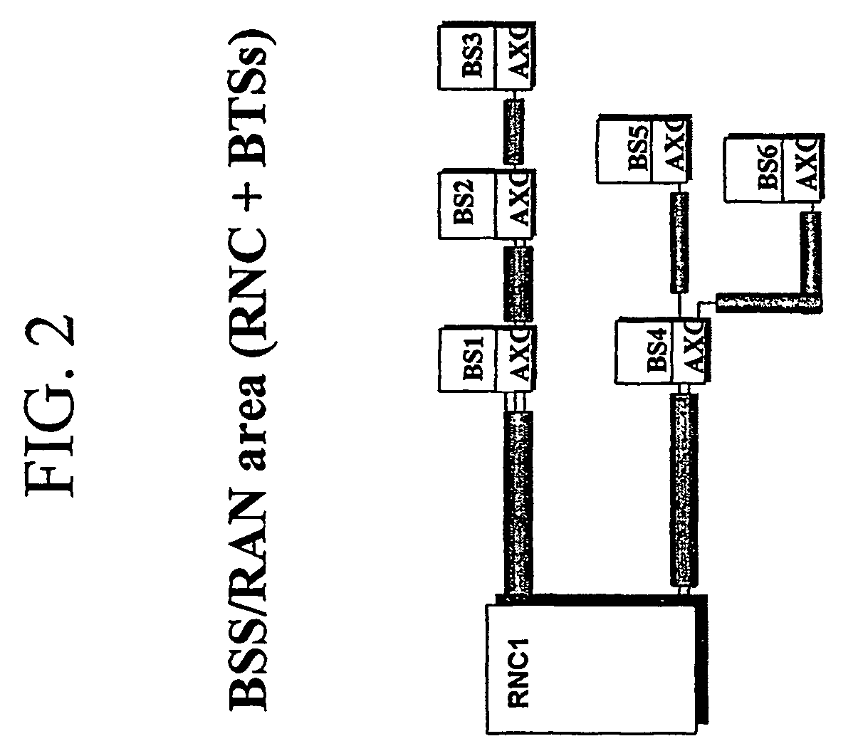
[0047]According to the present invention, data transmission from different base stations BS (access nodes) experiences different delays and / or delay variations dependent on the position of the base stations in a chain of consecutively arranged base stations, the chain being connected at one end to a radio network controller (access network control node). Thus, it is possible to allow the base station imposing the least delay to consume more delay.

[0048]Generally spoken, as regards a communication connected to the access network control node by an intermediate of at least one access node, a delay information of the delay experienced by data transmission between a respective network access node and the access network control node is derived, a delay difference between two consecutive access nodes based on the delay information is calculated, and the delay experienced by data transmission for the respective access node...


PUM


Abstract

The present invention proposes a method for configuring a data transmission interface in a communication network adopting a transmission protocol for transmission of data in units of grouped data, wherein said transmission interface is the interface (Iub) between an access network control node (RNC1) and an access node (BS1-BS6) adapted to establish a communication to a terminal, and wherein said communication network has a topology such that an access node (BS2, BS3, BS5, BS6) is connected to said access network control node (RNC1) by an intermediate of at least one further access node (BS1,BS1-BS2, BS4, BS4), said method comprising the steps of: deriving a delay information of the delay experienced by data transmission between a respective network access node (BS1-BS6) and said access network control node (RNC), calculating a delay difference between two consecutive access nodes (BS1-BS2, BS2-BS3, BS4-BS5, BS4-BS6) based on said delay information, and modifying the delay experienced by data transmission for the respective access node which is identified by the respective smaller delay. Also, the present invention proposes an accordingly adapted access network control node as well as accordingly adapted access nodes.

Description

BACKGROUND OF THE INVENTION[0001]1. Field of the Invention[0002]The present invention relates to a method for configuring a data transmission interface in a communication network adopting a transmission protocol for transmission of data in units of grouped data.[0003]2. Description of the Prior Art[0004]Typically, a communication network comprises a core network which is independent of the connection technology used and handles “administrative” topics occurring in the network, as well as an access network. The access network is in charge of enabling terminals to access the communication network for communicating via the network with other terminals. The access network is dependent on the technology used for establishing connection with terminals (for example wireless or non-wireless connection).[0005]For explanatory purposes only, the present description focuses on a wireless access network which is commonly referred to as radio access network (RAN), which enables terminals to acces...

Claims


Application Information

Patent Timeline
Patent Type & Authority Patents(United States)
IPC IPC(8): H04L12/26H04W88/08H04W92/12
CPCH04W88/08H04L2012/5607H04L2012/5656H04W92/12
Inventor HOLMA, MAUNUISOKANGAS, JARIMETSALA, ESA
Owner NOKIA CORP
Why Eureka
Try Eureka