Shutter device and projection type video display

a technology of projection type and video display, which is applied in the direction of door/window protective devices, exposure control, instruments, etc., can solve the problems of reducing the reliability of liquid, increasing the temperature of liquid crystal display panels, and excessively increasing the temperature, so as to achieve easy formation and high processing accuracy

Active Publication Date: 2008-03-04
SANYO ELECTRIC CO LTD +1
View PDF12 Cites 19 Cited by
  • Summary
  • Abstract
  • Description
  • Claims
  • Application Information

AI Technical Summary

Benefits of technology

[0004]In view of the foregoing circumstances, it is an object of the present invention to provide a shutter device and a projection type video display which are capable of blocking incidence of light on a liquid crystal display panel or the like when image projection is stopped temporarily and controlling the amount of light at a plurality of stages.
[0009]In a shutter device of these configurations, it is desirable that the shading plate is formed by putting two approximately T-shaped plates together in opposite direction so as to form at least one of the aforementioned recess and the aforementioned thin-wall area. According to this, at least one of the recess and the thin-wall can be easily obtained.
[0011]It may be possible that divided shading plates are rotated independently by arranging two rotating shafts closely each other, but this will make a structure complicated. On the other hand, it is possible to avoid complicated structure, if divided shading plates are loosely fitted to the rotating shaft and rotated by a driving shaft provided separately from the rotating shaft.
[0014]Also, a shutter device according to the present invention is provided with a plurality of rectangular-shaped shading plates which form a shading state and a non-shading state by their rotating movement and a supporting member composed of a first member and a second member, and recesses are formed on at least one of the two members which form the supporting member, and rotating shafts for rotating the shading plates are supported by hole-shaped portions which are made by the recesses obtained by arranging the first member and the second member in parallel. In such a configuration, hole-shaped portions for rotating shafts can be easily formed, compared with the case where the hole-shaped portions are formed by using a drill, etc. Moreover, hole-shaped portions can be formed at the same intervals with the arranging pitch of the rotating shafts without requiring high processing accuracy.

Problems solved by technology

However, in a conventional mechanism in which light is shut off at a stage before the light enters a projection lens, illuminating light enters a liquid crystal display panel even while image projection is being shut off.
The temperature of a liquid crystal display panel is increased due to incidence of light, and excessive increase in temperature decreases reliability of liquid crystal layer, polarizing plate, or the like.

Method used


Image

  • Shutter device and projection type video display
  • Shutter device and projection type video display
  • Shutter device and projection type video display

Examples


Embodiment Construction

[0026]A liquid crystal projector and a shutter device according to an embodiment of the present invention are now described referring to FIGS. 1 to 5.

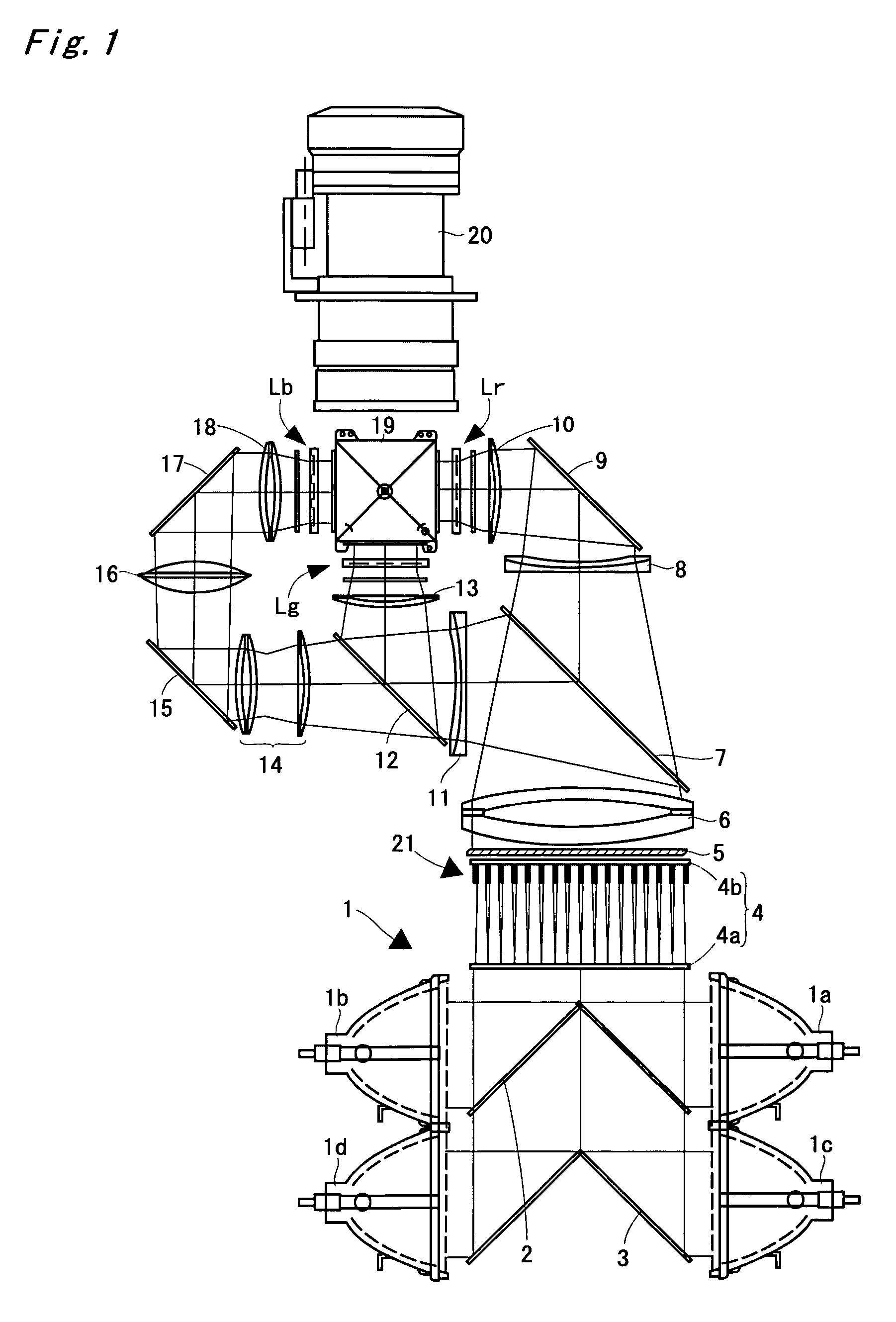
[0027]FIG. 1 is a diagram showing a four-lamp and three-panel liquid crystal projector according to an embodiment of the present invention. An illuminating device 1 comprises four light sources 1a, 1b, 1c, and 1d, a mirror 2 arranged between the light sources 1a and 1b, and a mirror 3 arranged between the light sources 1c and 1d. Each light source is composed of an ultra-high pressure mercury lamp, a metal halide lamp, a xenon lamp, or the like, and its irradiated light is emitted after being changed into parallel light by a parabolic reflector, to be guided into an integrator lens 4.

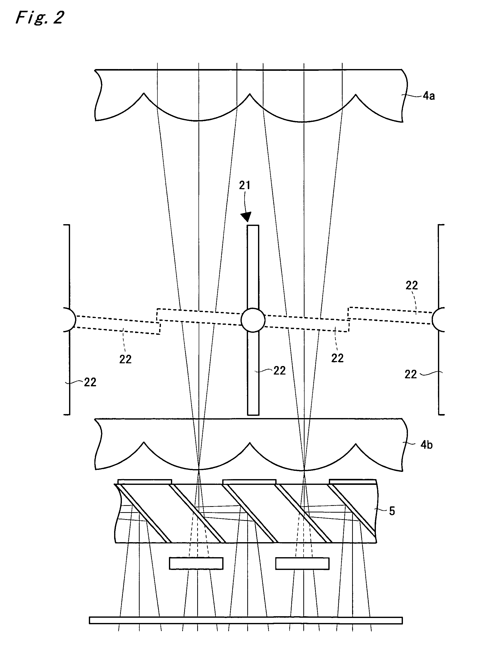
[0028]The integrator lens 4 comprises a pair of fly's eye lenses 4a and 4b. Each pair of lenses guides light emitted from the illuminating device 1 into the whole surface of a liquid crystal panel, described later, to even off local luminance non-uniformit...


PUM

PropertyMeasurementUnit
areaaaaaaaaaaa
concave areaaaaaaaaaaa
temperatureaaaaaaaaaa

Abstract

Each shading plate comprises a rotating shaft and a driving shaft arranged vertically. First divided shading plate is loosely fitted to and supported by (not adhere to) the rotating shaft and rotates around the shaft. Second divided shading plates are fixed to the rotating shafts and rotate by rotating movement of the shafts. A driving shaft is connected longitudinally to (not adhere to) an edge of the first divided shading plate and supply power to rotate the first divided shading plates. Recesses are formed at the center of upper short side and at the center of lower short side of the first divided shading plate and the first divided shading plate and the second divided shading plates which form one and the same shading plate are so constructed that their short sides are overlapped each other.

Description

BACKGROUND OF THE INVENTIONField of the Invention[0001]The present invention relates to a shutter device and a projection type video display with the shutter device.[0002]One of the ways of utilizing a liquid crystal projector is to receive a video signal outputted from a personal computer to project an image. That is, when a person who makes a presentation operates a personal computer to display an image which he or she wants participants of the presentation to see on a display of the personal computer, the same image is enlarged and projected on a screen by a liquid crystal projector, so that all the participants of the presentation can see the image. On the other hand, in some cases, the person who makes a presentation may not desire an image which appears in the course of operating the computer to be viewed by the participants. In order to cope with such cases, there has been proposed a liquid crystal projector equipped with a projection shutdown mechanism for temporarily interc...

Claims


Application Information

Patent Timeline
Patent Type & Authority Patents(United States)
IPC IPC(8): G03B21/14E06B9/30G02B3/08H04N9/31G02B26/02G02F1/13G03B21/16
CPCF21V11/04G02B27/285H04N9/3105H04N9/3141H04N9/3197
Inventor KOBA, HIROKIHOSHIDE, KAORUKOUCHI, MINORU
Owner SANYO ELECTRIC CO LTD
Why Eureka
Try Eureka