Eureka AIR delivers breakthrough ideas for toughest innovation challenges, trusted by R&D personnel around the world.

Imaging lens

a technology of imaging lens and aberration correction, applied in the field of imaging lens, can solve the problems of difficult to achieve both satisfactory aberration correction and miniaturization, and achieve the effects of satisfactory aberration correction, satisfactory aberration correction, and reduced manufacturing cost of imaging lens

Active Publication Date: 2012-08-09
TOKYO VISIONARY OPTICS CO LTD
View PDF1 Cites 10 Cited by
  • Summary
  • Abstract
  • Description
  • Claims
  • Application Information

AI Technical Summary

Benefits of technology

[0010]When the imaging lens with the above configuration satisfies the conditional expression (1), it is possible to reduce a length (thickness) of the imaging lens along the optical axis while satisfactorily correcting an aberration.
[0013]When the imaging lens satisfies the conditional expression (2), it is possible to restrain an incident angle of a light beam emitted from the imaging lens to an imaging element within a certain range and restrain field curvature within satisfactory range, while shortening the thickness of the imaging lens. As well known in the art, for light beams that an imaging element can take, a maximum incident angle is set as an incident angle limit in view of an imaging element structure. A light beam outside the range of the maximum incident angle may result in an image with a dark periphery due to a shading phenomenon. For this reason, it is necessary to restrain the incident angle of a light beam emitted from the imaging lens to the imaging element within the certain range.
[0016]When the imaging lens satisfies the conditional expression (3), it is possible to reduce the thickness of the imaging lens and restrain the respective aberrations, which includes off-axis chromatic aberration of magnification, within satisfactory ranges in a well-balanced manner. When the value exceeds the upper limit “0.8”, the composite focal length of the first lens and the second lens is long in relative to the composite focal length of the third lens and the fourth lens, and a position of a principal point of the lens system moves to the image plane side, so that it is difficult to attain miniaturization of the imaging lens. Furthermore, an off-axis chromatic aberration of magnification is insufficiently corrected (that of a short wavelength increases in a minus direction in relative to that of a reference wavelength), which makes it difficult to obtain satisfactory imaging performance. On the other hand, when the value is below the lower limit “0.1”, the composite focal length of the first lens and the second lens is short in relative to the composite focal length of the third lens and the fourth lens, and refractive power of the lens system concentrates on the first lens and the second lens, so that it is difficult to restrain a spherical aberration and a coma aberration within satisfactory ranges in a well-balanced manner. Moreover, the incident angle of an off-axis light beam emitted from the imaging lens to the imaging element increases, so that it is difficult to restrain an incident angle of a light beam emitted from the imaging lens to the imaging element within a certain range.
[0021]When the imaging lens satisfies the conditional expressions (6) and (7), it is possible to further satisfactorily correct the axial chromatic aberration and off-axis chromatic aberration of magnification.
[0022]Furthermore, in the imaging lens having the above-described configuration, when a material of the first lens and a material of the fourth lens are same and a material of the second lens and a material of the third lens are same, the number of types of materials to compose the imaging lens is only two, so that it is possible to reduce the manufacturing cost of the imaging lens.
[0023]According to the imaging lens of the invention, it is possible to attain both miniaturization of the imaging lens and satisfactory aberration correction, and it is possible to provide a small-sized imaging lens with satisfactorily corrected aberrations.

Problems solved by technology

However, as resolution of an imaging lens becomes higher, required optical performances become higher, so that it becomes difficult to attain both sufficient optical performances with satisfactorily corrected aberration and miniaturization.
In case of the lens configuration described in Patent Reference, it is difficult to attain both miniaturization and satisfactory aberration correction, so as to meet the above-described requirements.

Method used


Image

  • Imaging lens
  • Imaging lens
  • Imaging lens

Examples


first embodiment

[0036]Hereunder, referring to the accompanying drawings, a first embodiment of the present invention will be fully described.

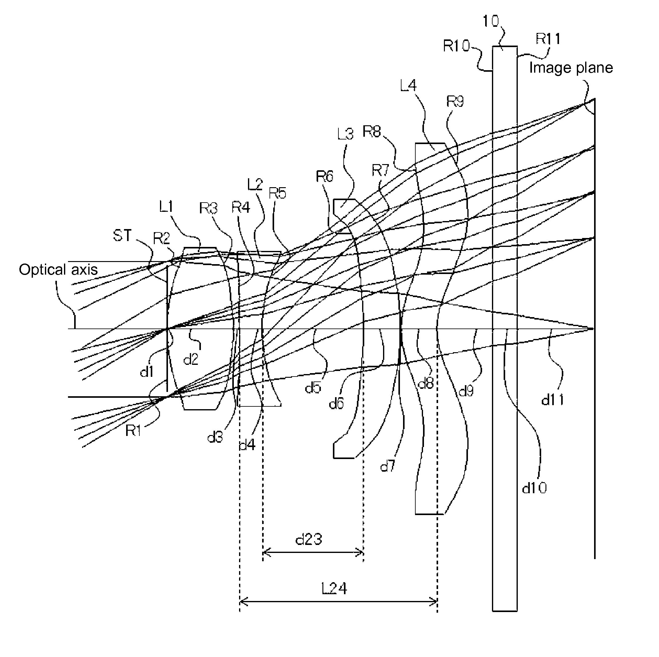
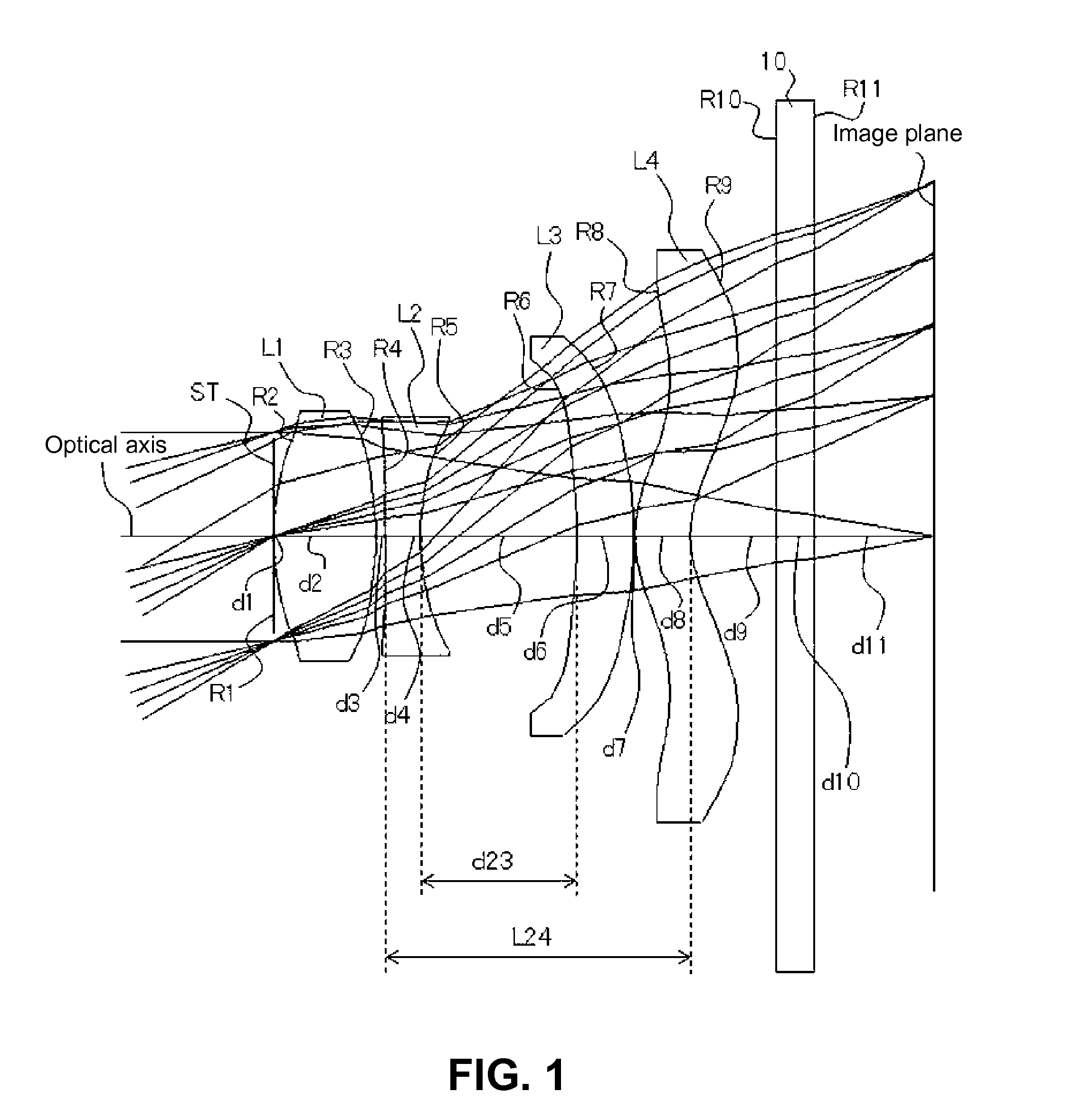
[0037]FIGS. 1, 4, and 7 are sectional views of imaging lenses in Numerical Data Examples 1 to 3 according to the embodiment, respectively. Since a basic lens configuration is the same among the Numerical Data Examples, the lens configuration of the embodiment will be described with reference to the lens sectional view of Numerical Data Example 1.

[0038]As shown in FIG. 1, the imaging lens of the embodiment has an aperture stop ST; a first lens L1 having positive refractive power; a second lens L2 having negative refractive power; a third lens L3 having positive refractive power; and a fourth lens L4 having positive refractive power, arranged in this order from an object side to an image plane side. A cover glass 10 is provided between the fourth lens L4 and the image plane. Here, the cover glass 10 may be optionally omitted. According to the embodiment, the ape...

second embodiment

[0090]Next, a second embodiment of the invention will be fully described referring to the accompanying drawings.

[0091]FIG. 10 shows a sectional structure of an imaging lens of Numerical Data Example 4, which is a numerical data example of this embodiment. As shown in FIG. 10, the imaging lens of this embodiment has an aperture stop ST; a first lens L1 having positive refractive power; a second lens L2 having negative refractive power; a third lens L3 having negative refractive power; and a fourth lens L4 having positive refractive power arranged in this order from an object side to an image plane side. A cover glass 10 is provided between the fourth lens L4 and the image plane. In addition, also in this embodiment, the aperture stop is provided on a tangential plane of a vertex of an object-side surface of the first lens L1.

[0092]In the imaging lens having the above-described configuration, the first lens L1 is formed in a shape so that a curvature radius R2 of an object-side surfac...


PUM


Abstract

An imaging lens includes a first lens having positive refractive power; a second lens having negative refractive power; a third lens having positive refractive power; and a fourth lens having positive refractive power, arranged from an object side to an image plane side. In the first lens, a curvature radius on an object-side surface is positive and a curvature radius of an image-side surface is negative. In the second lens, curvature radii of an object-side surface and an image-side surface are both positive. In the third lens, curvature radii of an object-side surface and an image-side surface thereof are both negative. When the whole lens system has a focal length f and a distance from the object-side surface of the first lens to an image-side surface of the fourth lens is L14, the imaging lens satisfies the following expression:0.5<L14 / f<0.8

Description

CROSS-REFERENCE TO RELATED APPLICATIONS[0001]This is a continuation application of the prior PCT application PCT / JP2010 / 068442, filed on Oct. 20, 2010, pending, which claims priority from a Japanese patent application No. 2009-243049, filed on Oct. 22, 2009, the entire content of which is incorporated herein by reference.BACKGROUND OF THE INVENTION AND RELATED ART STATEMENT[0002]The present invention relates to an imaging lens for forming an image on an imaging element such as a CCD sensor and a CMOS sensor. In particular, the present invention relates to an imaging lens suitable for mounting in a relatively small camera such as a cellular phone, a digital still camera, a portable information terminal, a security camera, an onboard camera, and a network camera.[0003]An imaging lens for mounting in the above-described small-sized camera is required to have a small size, as well as sufficient optical performances that can be compatible with recent imaging elements with high resolution...

Claims


Application Information

Patent Timeline
Patent Type & Authority Applications(United States)
IPC IPC(8): G02B9/34
CPCG02B13/004
Inventor KUBOTA, YOJIKUBOTA, KENICHIHIRANO, HITOSHIKURIHARA, ICHIRO
Owner TOKYO VISIONARY OPTICS CO LTD
Why Eureka
Eureka Blog
Learn More