Test socket-lid assembly

a socket-lid assembly and socket-lid technology, applied in the direction of coupling device connections, instruments, fault locations, etc., can solve the problems of large mass and velocity of heat sinks, kinetic energy, damage to integrated circuits, etc., to achieve uniform heat transfer, long service life, and uniform clamping force

Inactive Publication Date: 2008-03-04
PROTOS ELECTRONICS
View PDF15 Cites 13 Cited by
  • Summary
  • Abstract
  • Description
  • Claims
  • Application Information

AI Technical Summary

Benefits of technology

[0011]It is an object of the present invention to provide an IC test socket with uniform contact on the interface between the pusher and the IC chip in a clamped position of the chip. It is another object to provide an IC test socket that ensures uniform distribution of the clamping force and uniform transfer of heat from the chip to the heat sink. Still another object is to provide a test socket where, in order to compensate for manufacturing inaccuracies and dimensional variations in IC chips, the chip clamping member has several degrees of freedom. It is another object to provide a test lid-socket assembly that is characterized by long service life, good heat-removing conditions, quick setting of an IC in the socket for testing, and convenience in use.
[0012]In general, the test lid-socket assembly of the present invention consists of a socket sub-assembly for holding an item to be tested, e.g., an IC chip, in place during testing, and a lid and pusher sub-assembly that is separated from the socket sub-assembly and that can be easily and quickly connected to the latter by means of a transversely sliding locking mechanism.
[0013]The socket sub-assembly consists of three main parts: a pin retainer, a socket body supported by the pin retainer, and a floating base insertable into the recess of the socket body. The construction of the socket sub-assembly is conventional, except that the socket body has recesses on its upper face for locking the spherical ends of spring plungers on the mating side of the lid sub-assembly and guiding elements on the socket and the lid for aligning the spring plungers with the respective openings of the socket body. The socket body has a plurality of holes for insertion of a plurality of pogo pins so that the lower contact ends of the pogo pins can project through the holes and be retained by the pin retainer to which the socket body is connected. The floating base is supported by the socket body via a set of uniformly distributed compression springs and has a possibility for vertical movements limited by heads of the screws threaded into the respective openings of the socket body.
[0014]The main distinguishing feature of the present invention is the construction of the lid sub-assembly that can be realized in several embodiments. According to one embodiment, the lid sub-assembly has a rectangular frame with a central opening for a pusher and a rectangular lid that is pivotally connected to the frame at one side of the latter so that the lid can be turned up to provide access to the recess of the socket for inserting the IC chip that has to be tested and for turning the lid down for clamping the IC chip in the position for testing. The pusher is made in the form of a cylindrical body with a lower flange and with two diametrically arranged shafts that are inserted into a vertical slot of the pusher body for limited freedom of movement in the vertical direction and that project radially outward from the cylindrical part of the pusher. These shafts are also inserted into respective openings formed in mating side walls of the lid in order to attach the pusher in the lid with possibility of rocking or pivotal movements of the pusher relative to the lid. The upper side of the lower flange of the pusher supports a plurality of compression springs uniformly distributed in the circumferential direction. In a closed and locked position of the lid, the aforementioned springs are compressed between the lower side of the lid and the lower flange of the pivotally installed pusher through a shim and, along with the rocking movement of the pusher in the lid, provide the pusher with auto-alignment in the vertical direction with uniform distribution of the pressure applied from the pusher to the IC chip in the socket. According to another embodiment, the pusher has a composite structure and consists of two parts, one of which is telescopically inserted into the other with a plurality of springs between both parts of the pusher. The second part of the pusher also is pivotally supported on two shafts which can slide in a vertical slot of the first part of the pusher. Such a construction provides the pusher with additional degrees of freedom and further improves properties of self-alignment and uniformity of distribution of pressure applied to the IC chip.

Problems solved by technology

Heat sinks have large mass and velocity, and therefore have kinetic energy when they strike an integrated circuit.
Impact forces created by heat sinks on integrated circuits often result in damage to the integrated circuits.
Common drawbacks of known test sockets consist of insufficiently uniform pressure on the interface between the pusher and the IC chip in a clamped position of the chip, lack of self-alignment, insufficient removal of heat from the tested chips during the test, short service life of the lid-socket assembly in case of frequent use, and relatively long time required for setting an IC chip in the socket for testing.

Method used


Image

  • Test socket-lid assembly
  • Test socket-lid assembly
  • Test socket-lid assembly

Examples


Embodiment Construction

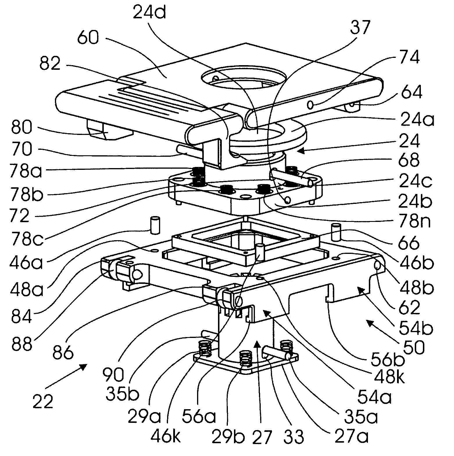
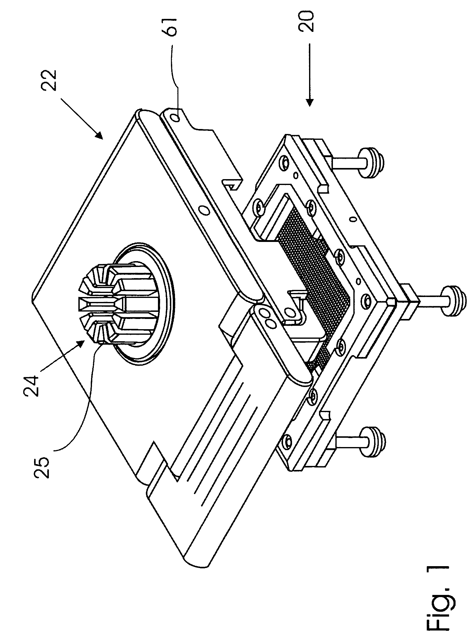
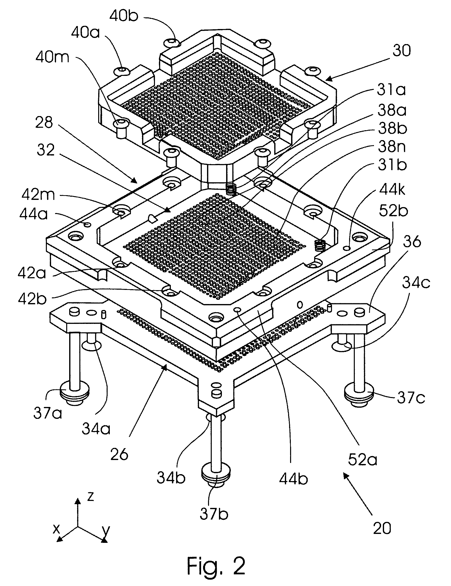
[0021]FIG. 1 is a general three-dimensional view of a lid-socket assembly of the invention for retaining electronic devices, e.g., IC chips, in a fixed position for testing their properties. It can be seen that the assembly consists of a socket sub-assembly 20 and a lid sub-assembly 22 that can be quickly and easily attached to the socket sub-assembly 20 by means of a locking mechanism (not shown in FIG. 1). Furthermore, the lid-sub-assembly supports a pusher 24, only a heat-sink portion 25 of which is seen in FIG. 1. FIG. 2 is an exploded three-dimensional view of the socket sub-assembly 20, and FIG. 3 is an exploded three-dimensional view of the lid sub-assembly 22. The pusher 24 may be realized in different embodiments. In the embodiment shown in FIG. 1, the heat sink member 25 is formed on the upper end of the pusher and projects outward through the central opening of the lid sub-assembly 22. FIG. 4 is a three-dimensional view of a lid sub-assembly 22′ in a closed state with a h...


PUM


Abstract

A test socket-lid assembly for testing electronic devices such as IC chips consists of a socket sub-assembly and a lid-sub-assembly, which is separated from the socket sub-assembly. In the lid sub-assembly, the lid is pivotally connected to the frame and supports a spring-loaded pusher that can slide in a vertical direction relative to the lid and can perform rocking movements relative to the lid. The assembly is distinguished from existing devices of this type in that the IC chip is supported and clamped in the lid sub-assembly and in that the entire lid sub-assembly together with the clamped and spring-loaded pusher is attached to the socket by guiding the lid sub-assembly in a transverse direction along the socket guide to the position wherein the spring plungers are locked into their respective openings on the surface of the socket. In one embodiment the pusher is a single part that has three degrees of freedom relative to the IC chip; in another embodiment, the pusher is of a composite structure and has five degrees of freedom.

Description

FIELD OF THE INVENTION[0001]The invention relates to devices for testing integrated-circuit chips, in particular to test socket-lid assemblies for holding integrated-circuit chips during testing.BACKGROUND OF THE INVENTION[0002]Increased capabilities of integrated-circuit chips (hereinafter referred to as IC chips) have led to increased input / output (I / O) densities and modified techniques for mounting IC chips to printed circuit (PC) boards involving IC chips. In view of the above, designs of IC test sockets for holding IC chips during their temporary connection to testing equipment are constantly being improved and modified. The existing lid-socket assemblies can roughly be divided into two main groups: (1) socket assemblies wherein the lid subassembly is separated from the socket sub-assembly and can be connected to the latter by clamps or locking mechanisms; and (2) socket assemblies wherein the lid sub-assembly is constantly pivotally connected to the socket.[0003]For example, U...

Claims


Application Information

Patent Timeline
Patent Type & Authority Patents(United States)
IPC IPC(8): H01R13/62
CPCH01R12/88H01R13/24H01R2201/20
Inventor WOODEN, GREGG
Owner PROTOS ELECTRONICS
Why Eureka
Try Eureka