Inductor

a technology of inductor coils and manufacturing processes, applied in the direction of transformers/inductance details, inductances, magnetic core inductances, etc., can solve the problems of increasing production costs, complicated manufacturing processes, and insufficient compact form factors of inductor coils manufactured with current technology, etc., to achieve improved form factors, reduce manufacturing costs, and simplify manufacturing processes

Active Publication Date: 2008-03-04
CYNTEC
View PDF3 Cites 35 Cited by
  • Summary
  • Abstract
  • Description
  • Claims
  • Application Information

AI Technical Summary

Benefits of technology

[0009]It is therefore an object of the present invention to provide a new structural configuration and manufacture method for manufacturing an inductor with simplified manufacturing processes to produce inductors with improved form factors having smaller height and size and greater device reliability.
[0010]Specifically, this invention discloses an inductor that includes conducting wire-winding configurations that are more compatible with automated manufacturing processes for effectively reducing the production costs. Furthermore, with enhanced automated manufacturing processes, the reliability of the inductors is significantly improved.

Problems solved by technology

For those of ordinary skill in the art, the configurations and the process of manufacturing a high current inductor coil are still faced with technical challenges that inductor coils manufactured with current technology still do not provide sufficiently compact form factors often required by applications in modern electronic devices.
Furthermore, conventional inductor coils are still manufactured with complicated manufacturing processes that involve multiple steps of epoxy bonding and wire welding processes.
The production cost is also increased due to the requirements that the lead frame and the coil must be separately manufactured.
The manufacture processes are further complicated since several welding and bonding steps are required to securely attach the welding ends of the flat wire to the welding points of the lead frame.
The production yields and time required to manufacture the inductor coil are adversely affected due to the more complicated inductor configurations and multiple bonding and welding manufacturing processes.
These inductors however have a difficulty that the inductor reliability is often a problem.
Additionally, the manufacturing methods are more complicated and the production costs are high.
The high production costs are caused by the reasons that the configurations are not convenient for using automated processes.
Thus, the inductors as disclosed do not enable a person of ordinary skill to perform effective cost reduction in producing large amounts of inductors as now required in wireless communications.

Method used


Image

  • Inductor
  • Inductor
  • Inductor

Examples


Embodiment Construction

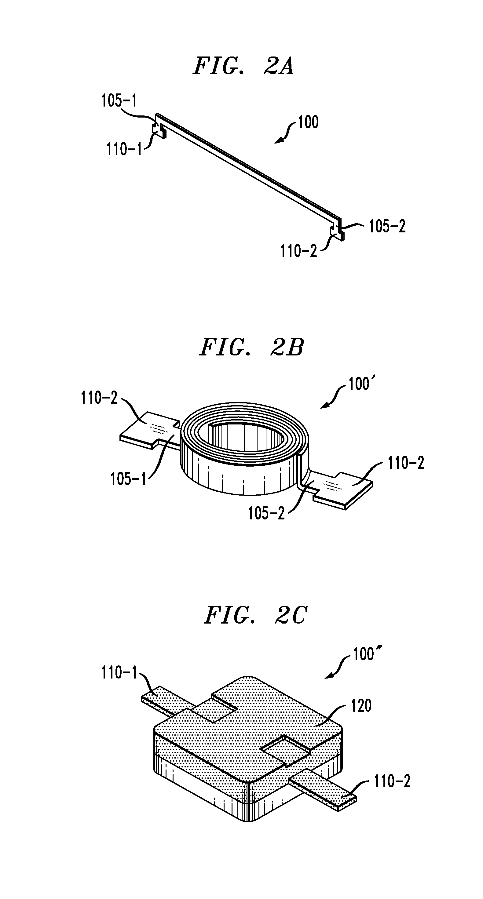
[0020]Referring to FIGS. 2A to 2D, a series of perspective views illustrate manufacturing processes of this invention. In FIG. 2A, a conductive flat wire 100 includes a first terminal extension 105-1 extended from a first end of the flat wire 100 connected to a first terminal plate 110-1. The flat wire 100 further has a second terminal extension 105-2 extended from a second end of the flat wire 100 and connected to a second terminal plate 110-2. In FIG. 2B, the flat wire 100 is rolled up as a coil 100′ and the terminal extensions 105-1 and 105-2 are bent to extend away from the first and second ends of the rolled up coil 100′. The configuration has an advantage that the manufacturing processes are simplified because the flat wire 110 and terminal plates 110-1 and 110-2 can be formed by simply applying a metal pressing process. The coil further has an easily manageable form factor with a controllable outside diameter. The manufacturing processes are also simplified without requiring ...


PUM

PropertyMeasurementUnit
diameteraaaaaaaaaa
diametersaaaaaaaaaa
diameteraaaaaaaaaa

Abstract

This invention discloses an inductor including a conducting wire having a winding configuration provided for enclosure in a substantially rectangular box with a mid-plane extended along an elongated direction of the rectangular box wherein the conducting wire intersecting at least twice near said mid-plane.

Description

BACKGROUND OF THE INVENTION[0001]1. Field of the Invention[0002]This invention relates generally to the device configuration and processes for manufacturing inductor coils. More particularly, this invention relates to an improved configuration and process for manufacturing compact and high current inductor coils.[0003]2. Description of the Prior Art[0004]For those of ordinary skill in the art, the configurations and the process of manufacturing a high current inductor coil are still faced with technical challenges that inductor coils manufactured with current technology still do not provide sufficiently compact form factors often required by applications in modern electronic devices. Furthermore, conventional inductor coils are still manufactured with complicated manufacturing processes that involve multiple steps of epoxy bonding and wire welding processes.[0005]Shafer et al. disclose a high current low profile inductor in U.S. Pat. No. 6,204,744, as that shown in FIG. 1. The induc...

Claims


Application Information

Patent Timeline
Patent Type & Authority Patents(United States)
IPC IPC(8): H01F5/00
CPCH01F17/04H01F27/027H01F27/255H01F27/2828H01F27/292H01F2017/046H01F2017/048
Inventor LIU, CHUN-TIAOCHEN, STANELYHSIEH, ROGERHUANG, YIMINCHUANG, WEI-CHING
Owner CYNTEC
Why Eureka
Try Eureka