Photonic crystal exhibiting negative refraction without requiring a negative effective index

a technology of effective index and photonic crystal, which is applied in the field of material and device for use with electromagnetic fields, can solve the problems of limited material availability, and achieve the effect of reducing the number of materials

Inactive Publication Date: 2008-03-04
MASSACHUSETTS INST OF TECH
View PDF11 Cites 57 Cited by
  • Summary
  • Abstract
  • Description
  • Claims
  • Application Information

AI Technical Summary

Benefits of technology

[0013]In further embodiments, the periodic electromagnetic medium has a positive effective index and includes a first surface for receiving an incident electromagnetic field having a first wavelength, a second surface for producing a focused electromagnetic field, and a periodic structure for providing a focal spot size that is smaller than the first wavelength.
[0014]In still further embodiments, the dielectric periodic electromagnetic medium may include a first surface for receiving an incident electromagnetic field having a first wavelength, a second surface for producing a focused electromagnetic field, and a periodic structure for providing a focal spot size that is smaller than the first wavelength.

Problems solved by technology

Such materials, however, are typically limited by the physical size of the metallic components in the structure that provide the negative permittivity and negative permeability under the appropriate radiation frequencies.

Method used


Image

  • Photonic crystal exhibiting negative refraction without requiring a negative effective index
  • Photonic crystal exhibiting negative refraction without requiring a negative effective index
  • Photonic crystal exhibiting negative refraction without requiring a negative effective index

Examples


Embodiment Construction

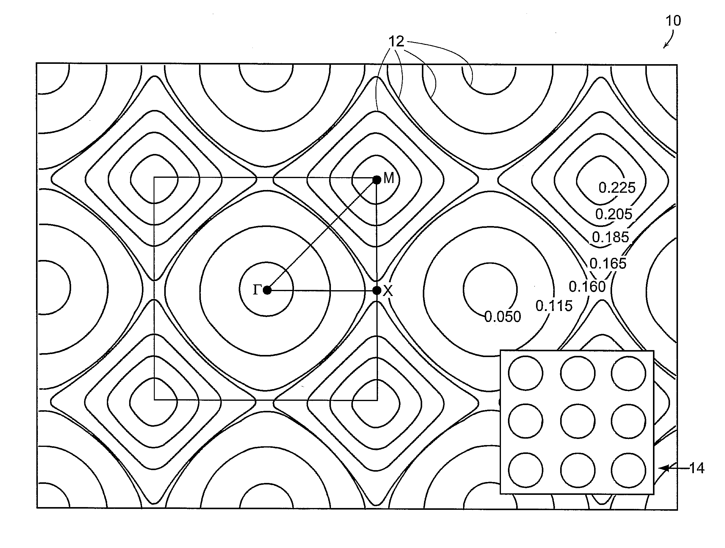
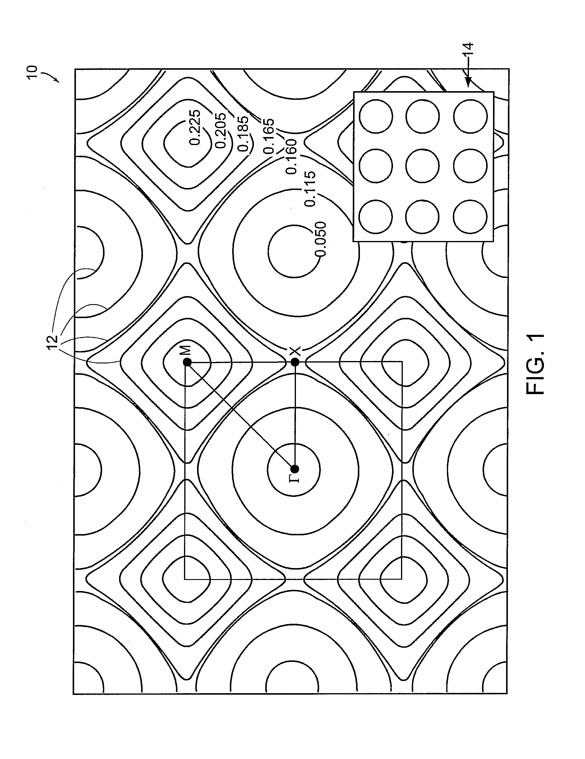
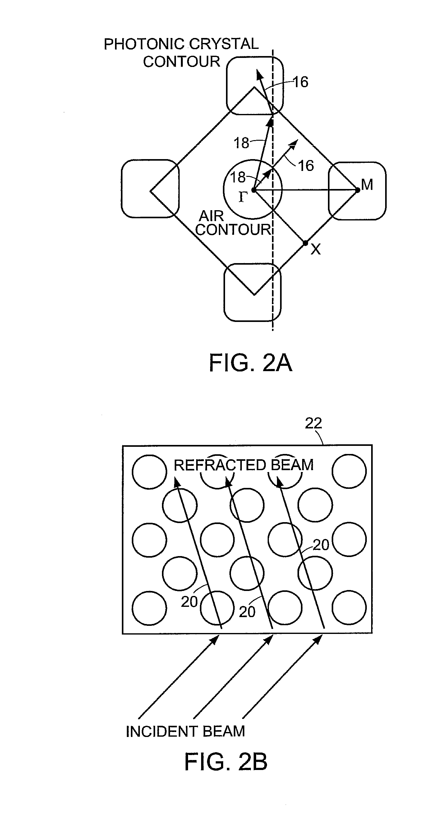
[0042]The invention provides an all-angle negative refraction effect for photonic crystals that does not employ a negative effective index of refraction. In accordance with an embodiment, a micro-superlens is described and numerically demonstrated. It has also been discovered that negative refraction may be achieved without employing materials with negative effective index. In particular, the lowest photonic band near a Brillouin zone corner furthest from Γ may actually be employed in an embodiment of the invention. This band has a positive group velocity and a positive refractive index, but a negative photonic effective mass. A single, negative-refracted beam may be achieved, therefore, for all incident angles at the selected frequency range. Such all-angle negative refraction (AANR) is essential for superlens applications.

[0043]For a two-dimensional photonic crystal, a square lattice of air holes in dielectric ε=12.0 (e.g. Si at 1.55 μm) is consider with lattice constant a and hol...


PUM


Abstract

A periodic electromagnetic medium is disclosed that includes a surface that provides an interface with an ambient medium and a periodic structure that provides negative refraction within the medium of an incident electromagnetic field incident on the surface. In various embodiments the incident electromagnetic field is within a range of frequencies, the medium may include dielectric or metallic material, and has either a positive or negative effective index.

Description

PRIORITY INFORMATION[0001]The present application claims priority to U.S. Provisional Patent Application Ser. No. 60 / 370,977 filed Apr. 9, 2002; and U.S. Provisional Patent Application Ser. No. 60 / 407,169 filed Aug. 30, 2002.[0002]This invention was made with government support under Grant No. DMR-9808941 awarded by NSF. The government has certain rights in the invention.BACKGROUND OF THE INVENTION[0003]The invention relates to materials and devices for use with electromagnetic fields and relates in particular to materials and devices through which electromagnetic fields may be propagated in unconventional ways.[0004]For example, the propagation of electromagnetic fields at microwave frequencies through substances with negative values of electrical permittivity and magnetic permeability are disclosed in The Electrodynamics of Substances with Simultaneously Negative Values of ε and μ, by V. G. Veselago, SOVIET PHYSICS USPEKHI, vol. 10, No. 4 (January-February 1968). Such substances a...

Claims


Application Information

Patent Timeline
Patent Type & Authority Patents(United States)
IPC IPC(8): H01Q19/06H01Q15/02G02B6/10G02B6/12G02B6/122H01Q15/00H01Q15/10
CPCB82Y20/00G02B1/007G02B6/10G02B6/12G02B6/1225H01Q15/02H01Q15/10H01Q19/06H01Q15/0086
Inventor JOANNOPOULOS, JOHN D.LUO, CHIYANJOHNSON, STEVEN G.FINK, YOEL
Owner MASSACHUSETTS INST OF TECH
Why Eureka
Try Eureka