
Method and apparatus for processing video pictures improving dynamic false contour effect compensation

a dynamic false contour and video picture technology, applied in the field of video picture processing, can solve problems such as picture quality damage, failure of human beings, and picture quality reduction

Active Publication Date: 2008-03-04
INTERDIGITAL CE PATENT HLDG
View PDF7 Cites 12 Cited by
  • Summary
  • Abstract
  • Description
  • Claims
  • Application Information

AI Technical Summary

Benefits of technology

The invention proposes a new method for optimizing the coding of video pictures based on their activity in terms of motion and noise. The method involves dividing the picture into sub-fields and using different encoding methods for each sub-field based on the activity level of the picture. The first method is used for static pictures and the second method is used for moving pictures. The method also adapts the noise dithering based on the presence of motion or noise. The technical effect of this invention is to improve the quality of video pictures by optimizing the coding based on their activity level and reducing the impact of noise.

Problems solved by technology

On one hand, the plasma display technology gives the possibility of nearly unlimited screen size, also of attractive thickness, but on the other hand, it generates new kinds of artefacts which could reduce the picture quality.
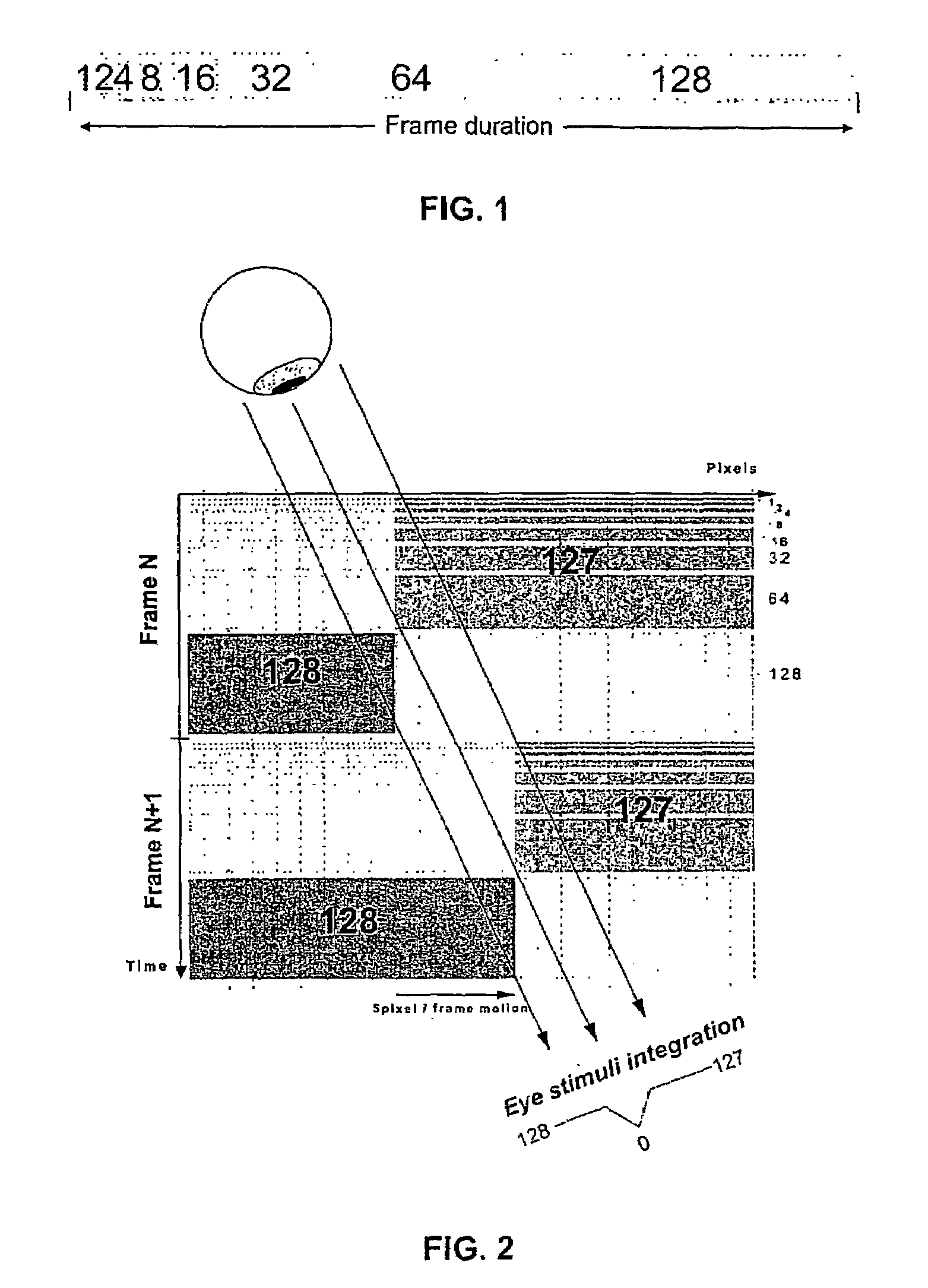
In addition, the same problem occurs on static images when observers are shaking their heads and that leads to the conclusion that such a failure depends on the human visual perception and happens on the retina of the eye.
However, due to the reduction of the number of gray levels to the number of sub-fields, the picture quality is really damaged.
Such a coding, while very good for moving sequences, is less efficient in case of still or non-moving pictures because of the dithering noise.

Method used


Image

  • Method and apparatus for processing video pictures improving dynamic false contour effect compensation
  • Method and apparatus for processing video pictures improving dynamic false contour effect compensation
  • Method and apparatus for processing video pictures improving dynamic false contour effect compensation

Examples


Embodiment Construction

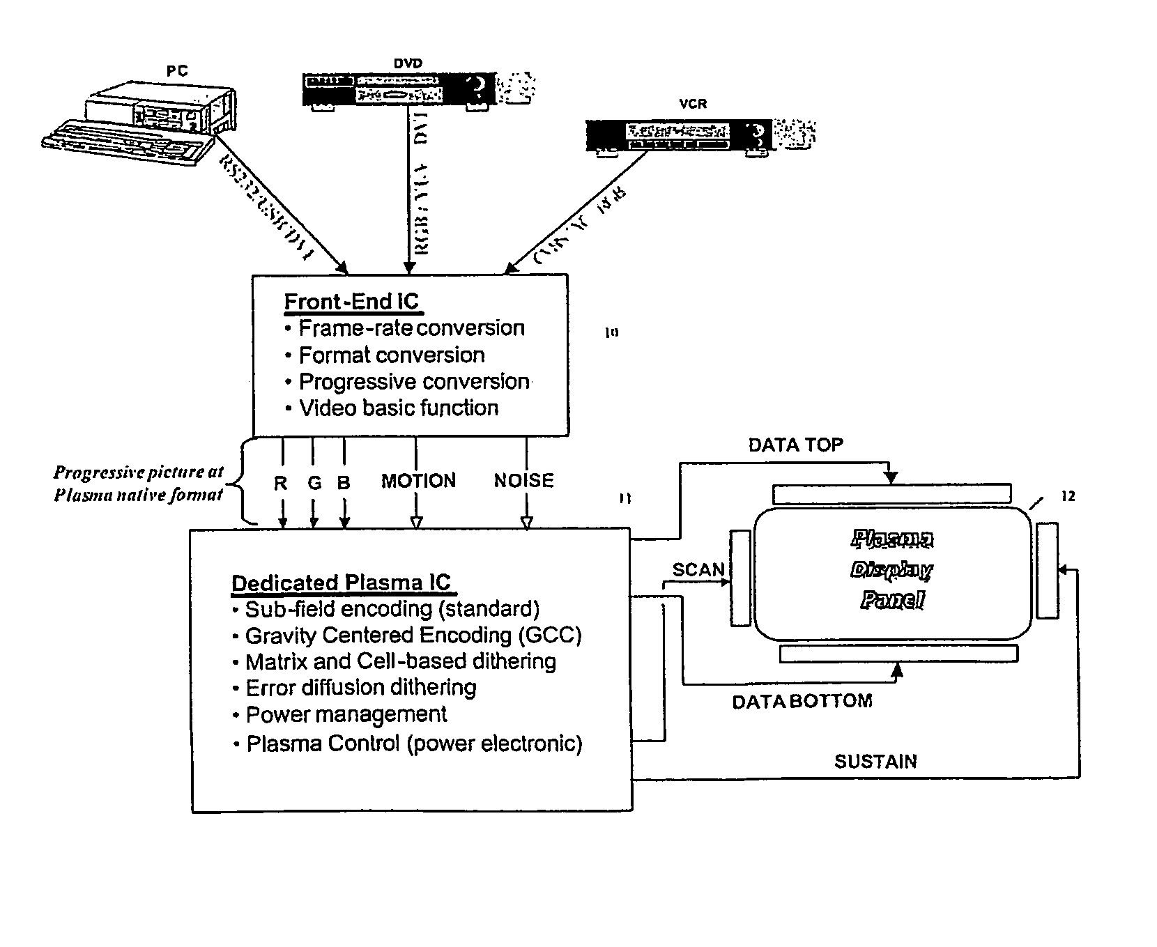
[0106]The present invention relates to a method improving false contour effect compensation in matrix displays screens using a PWM modulation of light emission, for example in plasma display panels. According to the method of the present invention, a first sub-field encoding method, more particularly the standard encoding method is used when no motion is detected and a second sub-field encoding method is used when motion is detected.

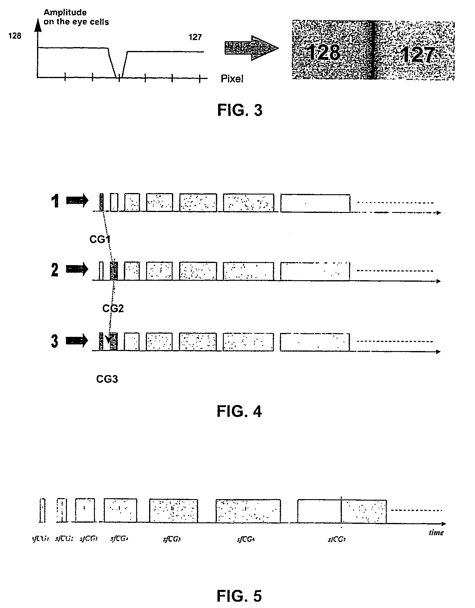
[0107]As known, plasma display panel (PDP) utilises a matrix array of discharge cells. In this case, gray levels can not be expressed by analog control of the light emission. So, a PDP controls gray levels by a plulse width modulation (PWM) of each cells, i.e. by modulating the number of light pulses per frame period. This time modulation will be integrated by the eye over a period corresponding to the eye time response. The more often a cell is switched on in a given time frame, the higher is its luminance. According to the standard coding scheme, a min...


PUM


Abstract

The invention relates to a method for processing video pictures for display on a display device having a plurality of luminous elements corresponding to the pixels of a picture wherein the time of a video frame or field is divided into a plurality of N sub-fields during which the luminous elements can be activated for light emission in small pulses corresponding to a sub-field code word of n bits used for coding the p possible video levels lighting a pixel, comprising the steps of:determining if pictures are static pictures or moving pictures,in case of static pictures, processing video pictures using a first sub-field encoding method adapted to pictures when no motion is detected, andin case of moving pictures, processing video pictures using a second encoding method reducing dynamic false contour effect adapted to pictures when motion is detected. The invention applies to plasma display panels.

Description

[0001]This application claims the benefit, under 35 U.S.C. § 365 of International Application PCT / EPO3 / 50232, filed Jun. 17, 2003, which was published in accordance with PCT Article 21(2) on Jan. 8, 2004 in English and which claims the benefit of European patent application No. 02291612.6, filed Jun. 28, 2002.FIELD OF THE INVENTION[0002]The present invention relates to a method for processing video pictures, especially a method improving dynamic false contour effect compensation in matrix display screens based on the principle of duty cycle modulation (PWM for Pulse Width Modulation) of light emission. The invention also relates to an apparatus for carrying out the method. The invention will be described in relation with plasma display panels (PDPs) but may be applicable to all kinds of displays based on the principle of duty cycle modulation such as DMD (Digital Micro-mirror Devices) or similar.BACKGROUND OF THE INVENTION[0003]Although plasma display panels are known for many years...

Claims


Application Information

Patent Timeline
Patent Type & Authority Patents(United States)
IPC IPC(8): H04N9/12H04N5/21H04N5/66G09G3/36G06T5/00G06T5/20G06T7/20G09G3/20G09G3/28
CPCG06T5/20G06T7/202G09G3/2029H04N5/213G06T5/003G09G3/2051G06T2207/10016G09G3/28G09G2320/0261G09G2320/0266G06T7/231G06T5/73
Inventor WEITBRUCH, SEBASTIENTHEBAULT, CEDRICCORREA, CARLOSDOSER, INGO
Owner INTERDIGITAL CE PATENT HLDG
Learn More