Grounding system for a rotating shaft

a rotating shaft and grounding system technology, applied in the direction of electrostatic charges, emergency protective circuit arrangements, and arrangements responsive to excess voltage, can solve the problems of shaft induced current, high common mode voltage (cmv) generation, and buildup of charge on the shaft surfa

Active Publication Date: 2008-03-04
ILLINOIS TOOL WORKS INC
View PDF8 Cites 33 Cited by
  • Summary
  • Abstract
  • Description
  • Claims
  • Application Information

AI Technical Summary

Problems solved by technology

A drawback to the use of AC motors with variable speed drives is that higher common mode voltage (CMV) is generated by the variable speed drive that increases shaft induced currents.
While the motor is running, the bearings become more resistive to current flow, causing a buildup of charge on the shaft surfaces.
This discharge causes electric discharge machining (EDM), which can damage the surfaces of the bearing races and the balls in the bearing.
Both the fusion crater and the particulate material in the bearing act to disturb the free flow rotation of the bearing, which can lead to physical damage and premature bearing failure.
Copper brushes, however, wear out quite rapidly and require frequent, periodic service and replacement.
Additionally, oxide build-up on the shaft and other barriers between the brushes and the shaft reduce the current flow and cause a burst of electrical energy across the brush and shaft.
Spring-loaded brushes also tend to vibrate due to alternating frictional stick / slip relationships between the brush and the shaft surface.
Vibration of the brushes, from whatever cause, can result in undesirable sparking.
With the exception of the fiber filaments, there is nothing to ensure that the filaments are properly aligned with respect to the motor shaft.

Method used


Image

  • Grounding system for a rotating shaft
  • Grounding system for a rotating shaft
  • Grounding system for a rotating shaft

Examples


Embodiment Construction

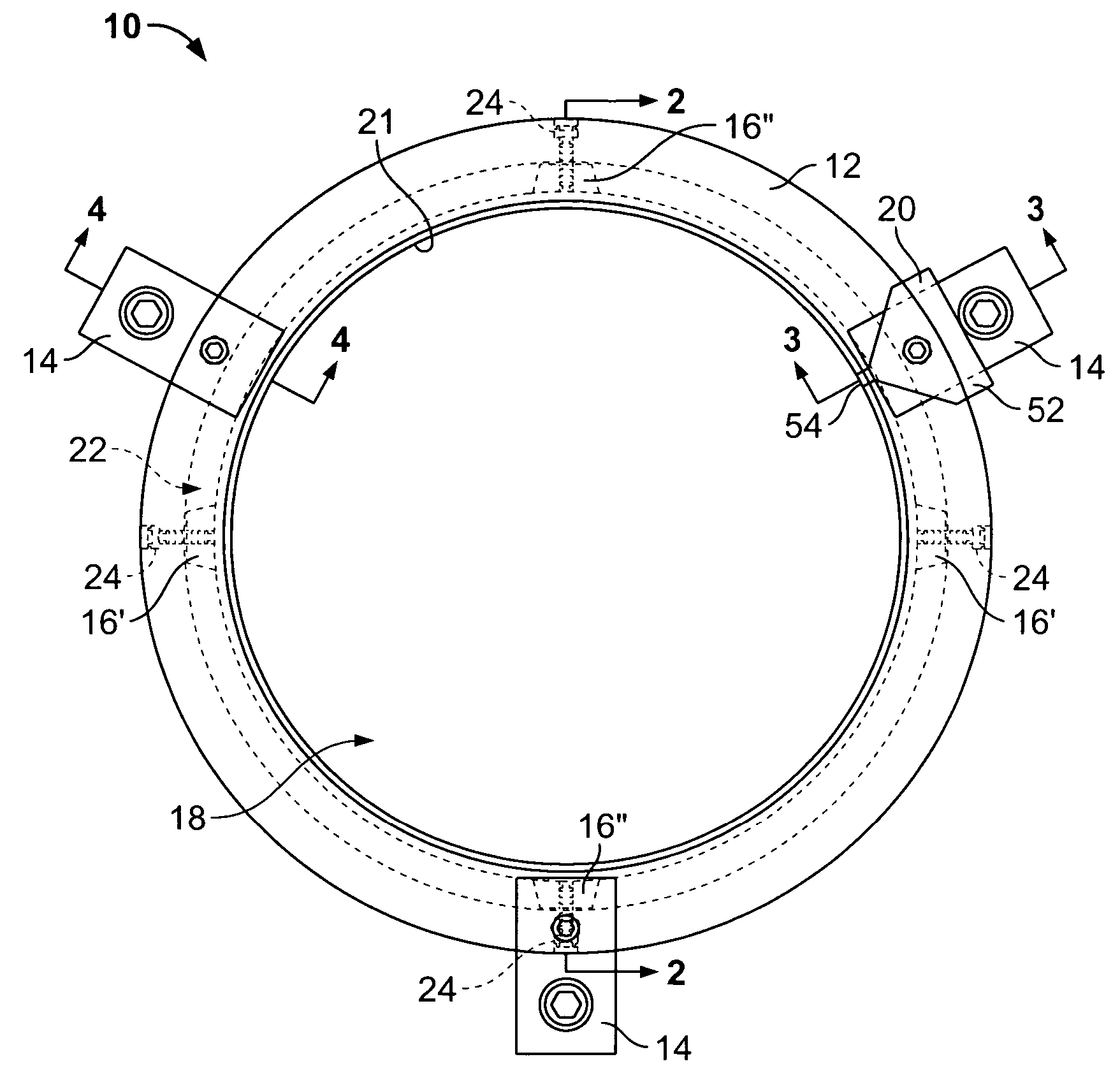
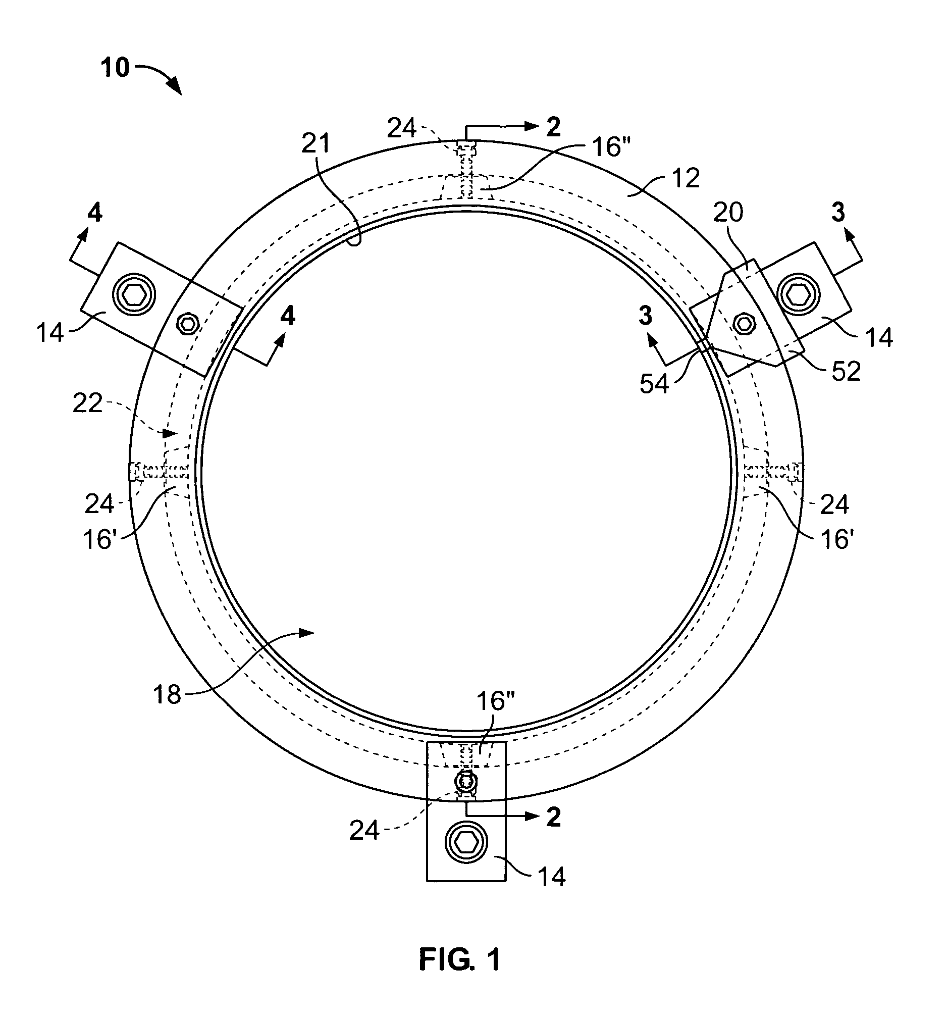
[0025]FIG. 1 illustrates a plan view of an electrical charge-dissipating assembly 10, according to an embodiment of the present invention. The assembly 10 includes an annular frame 12 housing a plurality of grounding fibers, or filaments, (not shown in FIG. 1), a plurality of mounting brackets 14 secured to the annular frame 12, and a plurality of wedge-shaped fiber clamps 16 positioned within the annular frame 12. The electrical charge-dissipating assembly 10 may be formed of metal, conductive plastic, or other electrically conductive materials. The electrical charge-dissipating assembly 10 is readily adaptable for use on motors of various sizes, having motor shafts of various diameters, and is operable to dissipate static and / or other such electrical charges that build on a motor shaft during operation of the motor.

[0026]The annular frame 12 includes a central opening 18 that defines a rotatable shaft passage, such as a motor shaft passage. The annular frame 12 is configured to be...


PUM


Abstract

A system is provided for dissipating electrical charges that build on a rotatable shaft extending from an electrically-grounded motor housing or rotating shafts conductively linked to components that create and electrical charge, such as wind turbine blades, power generator turbines, and the like. The system includes a frame defining a central opening wherein the rotatable shaft is positioned with the central opening, a first grounding fiber secured within the frame, and a fiber clamp positioned with the frame. The fiber clamp acts to urge the first grounding fiber toward the central opening. The system may also include a mounting bracket having a frame mounting channel, wherein a portion of the frame is securely retained within the frame mounting channel, and an installation guide positioned on the mounting bracket. The installation guide may be configured to properly align the frame and the first grounding fiber relative to the rotatable motor shaft.

Description

FIELD OF THE INVENTION[0001]Embodiments of the present invention generally relate to a grounding device for controlling shaft electrical current that is generated in AC motors controlled by variable speed drives or DC motors, and more particularly to a grounding ring apparatus for mitigating shaft electrical current. Additionally, embodiments of the present invention may be used in systems including rotating shafts conductively linked to components that create an electrical charge such as wind turbine blades, power generator turbines, and the like.BACKGROUND OF THE INVENTION[0002]Shaft induced electrical current is experienced in electrical motors, and is commonly experienced with three-phase motors driven by variable speed drives.[0003]Variable speed drives utilize pulse width modulation technology to vary the speed of AC motors, thereby allowing use of less-expensive AC motors in applications where more expensive DC motors had been used previously. A drawback to the use of AC moto...

Claims


Application Information

Patent Timeline
Patent Type & Authority Patents(United States)
IPC IPC(8): H05F3/02
CPCH01R39/64H02K11/0089H01R39/24H02K11/40
Inventor BARNARD, MICHAEL P.WILLWERTH, ADAM H.RICHARDSON, JEFFREY W.
Owner ILLINOIS TOOL WORKS INC
Why Eureka
Try Eureka