Data recording/reproducing apparatus, data recording/reproducing method, program, and recording medium

a data recording/reproducing and data technology, applied in the field of data recording/reproducing apparatus, data recording/reproducing method, program, and recording medium, can solve the problems of ineffective look-ahead operation, uneven data transfer rate, and large capacity of hard disk drives, so as to reduce the time of access

Inactive Publication Date: 2008-03-04
SONY CORP
View PDF17 Cites 9 Cited by
  • Summary
  • Abstract
  • Description
  • Claims
  • Application Information

AI Technical Summary

Benefits of technology

[0031]The present invention relates to a data recording / reproducing apparatus and a data recording / reproducing method for use with a randomly accessible recording medium, as well as a computer program and a recording medium for data recording and reproduction. More particularly, the present invention relates to techniques for causing a magnetic head to scan a magnetic disc medium such as a hard disc for writing and reading data to and from the medium, with emphasis on reducing the time of access to desired data storage locations on the medium during a stable data recording / reproducing operation.
[0032]The present invention provides in an embodiment a data recording / reproducing apparatus, a data recording / reproducing method, a computer program, and a storage medium for reducing the time for access to desired data locations in storage space.
[0033]The present invention provides in an embodiment a data recording / reproducing apparatus, a data recording / reproducing method, a computer program, and a storage medium for reproducing data stably without reducing data transfer rates.

Problems solved by technology

One disadvantage of this scheme is that the data transfer rate turns out uneven from one track to another.
The hard disc drive getting larger in capacity can no longer be dealt with by the CHS mode for lack of addressing capacity.
Where storage areas are so fragmented that large data are dispersed in small pieces over multiple locations, the look-ahead operation is ineffective because the operation points to discontinuous data.
This is how seek time and rotational delay occur.
That is, there are time losses due to seek time, rotational delay, and seeks getting initiated by look-ahead operations which turn out to be ineffective, as well as data losses caused by the ineffective look-ahead operations.
This measure is taken because of the difficulty in adopting an optimal access method since there is no regularity in the quantities and structures of data handled by the host (e.g., computers).
However, raising the disc revolutions is disadvantageous in terms of power dissipation and storage capacity.
Such retry operations, however, require waiting for the disc to make another turn for rereading the target data, which prolongs the data read time.
In such a case, uncorrectable errors within a sector cannot be retried for correction due to time constraints.
This has often resulted in reduced levels of image reproduction quality.
If a substantial number of sectors (e.g., dozens of sectors) are slipped per track, that translates into a considerable reduction in the effective per-track area of data sectors.
This has a detrimental effect on data transfer rates.
If vibrations or other external disturbances take place while AV content is being retrieved from the medium, more errors tend to occur than if such disturbances were nonexistent.
This means that there are more data which cannot be corrected for errors, so that reproduction quality is worsened.
In particular, if errors occur under external disturbances, more errors tend to occur intermittently in a sector segment flanked by servo areas located radially on the hard disc.
These errors may be random errors or burst errors.
In any case, the greater the magnitude of the external disturbance, the larger the number of sectors within which random errors cannot be corrected.

Method used


Image

  • Data recording/reproducing apparatus, data recording/reproducing method, program, and recording medium
  • Data recording/reproducing apparatus, data recording/reproducing method, program, and recording medium
  • Data recording/reproducing apparatus, data recording/reproducing method, program, and recording medium

Examples


first embodiment

1. First Embodiment

[0121]The first embodiment of this invention will now be described with reference to the accompanying drawings and under the following headings:

[0122]1-1. Structure of the Hard Disc Drive

[0123]1-2. Access Operations

[0124]1-3. ECC Structure

[0125]1-4. Processing According to Slip Status

[0126]1-1. Structure of the Hard Disc Drive

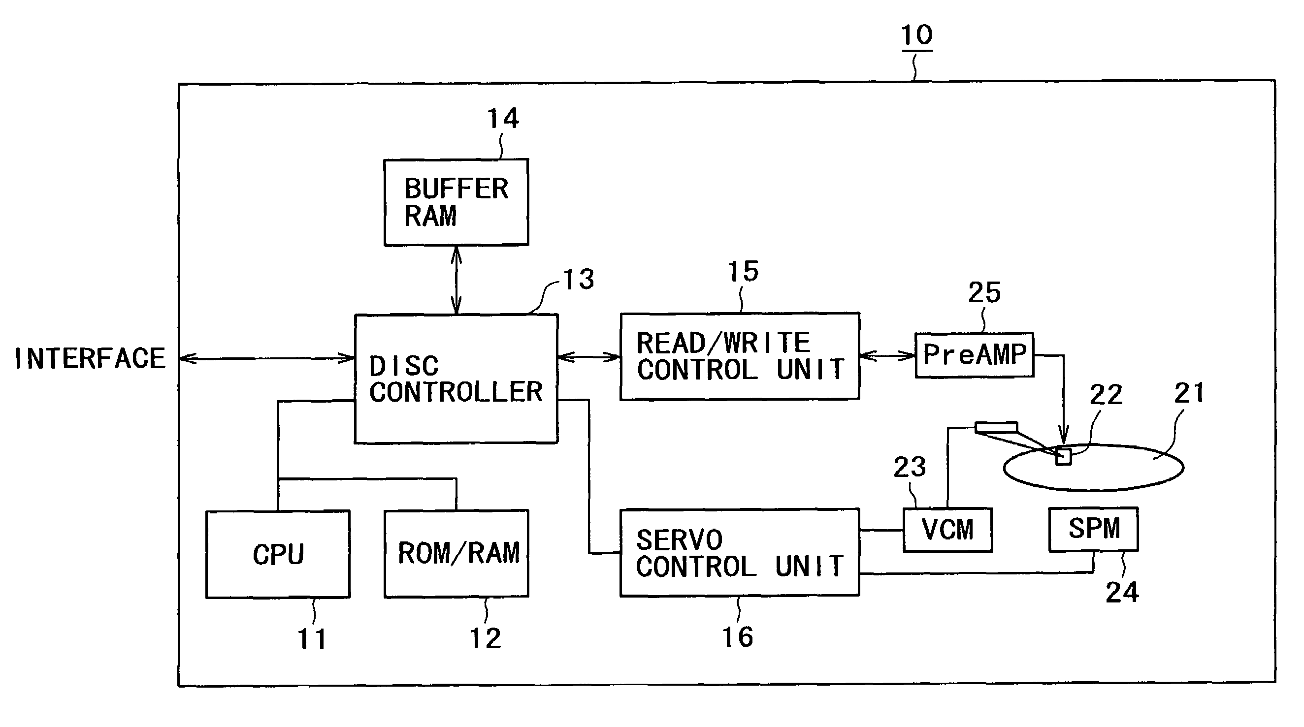
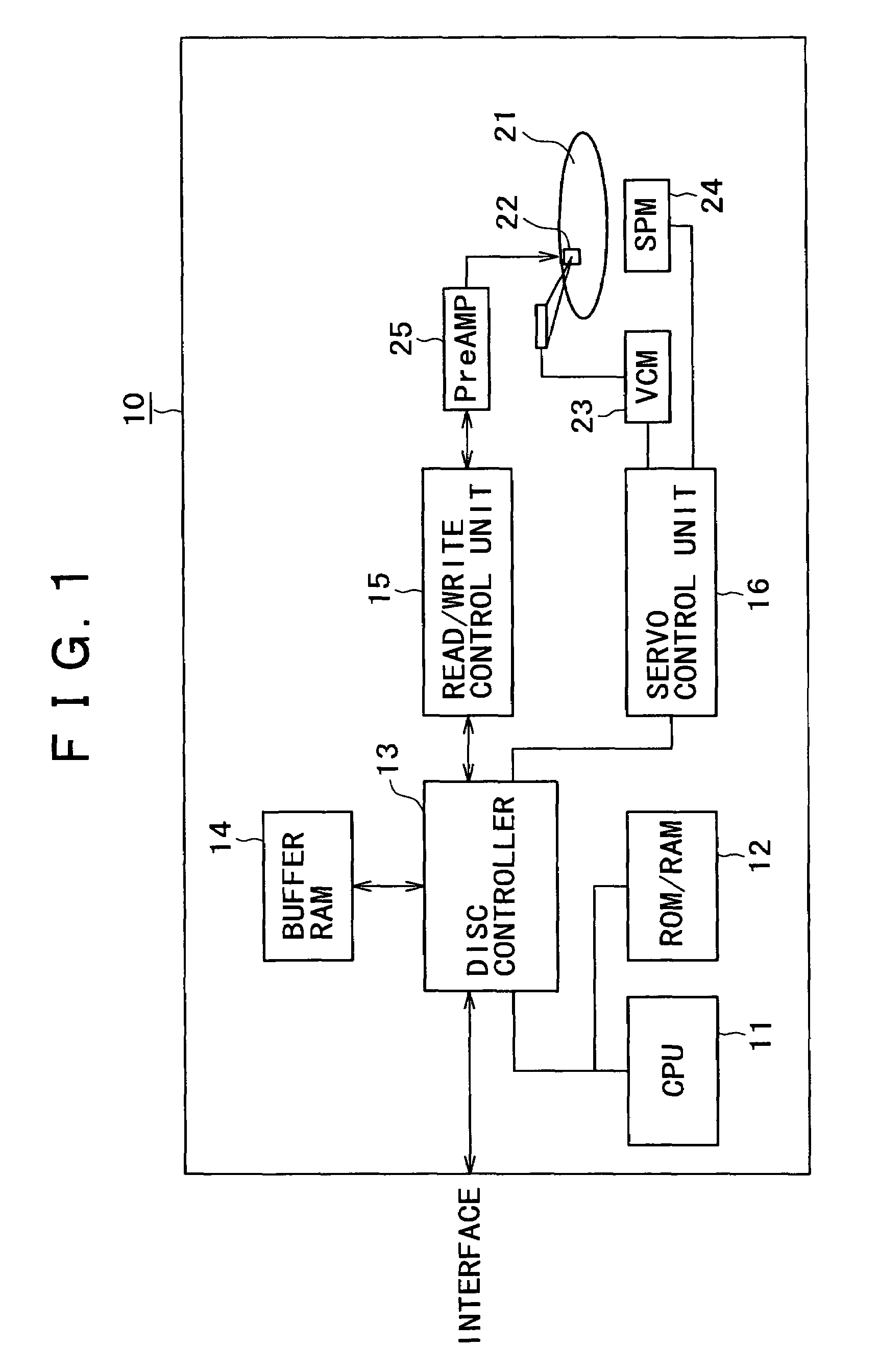
[0127]FIG. 1 schematically shows an overall structure of a hard disc drive (HDD) 10 practiced as the first embodiment of this invention. As illustrated, the HDD 10 includes a CPU (central processing unit) 11, a ROM (read only memory) / RAM (random access memory) 12, a disc controller 13, a buffer RAM 14, a data read / write control unit 15, a servo control unit 16, and a magnetic disc 21.

[0128]The CPU 11 provides overall control over the internal workings of the drive 10 by executing control codes held in the ROM / RAM 12. The disc controller 13 receives commands from a host (not shown) connected to the drive 10 via an interface 17. The CPU 11 proc...

second embodiment

2. Second Embodiment

[0237]2-1. Structure of the Hard Disc Drive

[0238]FIG. 1 schematically depicts an overall structure of a hard disc drive (HDD) 10 practiced as the second embodiment of this invention. As illustrated, the HDD 10 includes a CPU (central processing unit) 11, a ROM (read only memory) / RAM (random access memory) 12, a disc controller 13, a buffer RAM 14, a data read / write control unit 15, a servo control unit 16, and a magnetic disc 21.

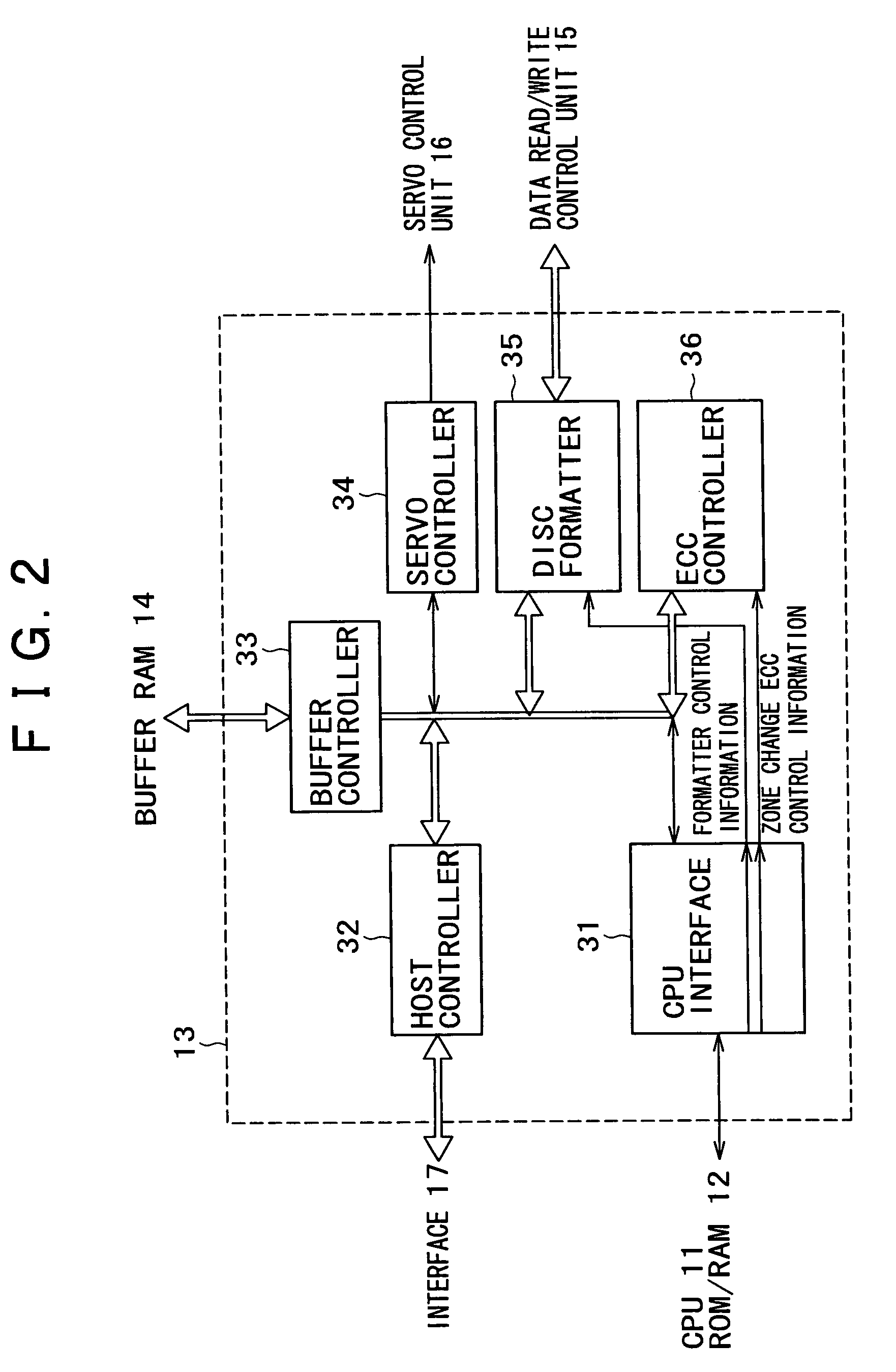
[0239]The CPU 11 provides overall control over the internal workings of the drive 10 by executing control codes held in the ROM / RAM 12. The disc controller 13 receives commands from a host (not shown) connected to the drive 10 via an interface 17. The CPU 11 processes the commands. In keeping with the results of the command processing, the disc controller 13 gives hardware operation instructions to the data read / write control unit 15 and servo control unit 16. Write data received from the host through the interface 17 or data retrieved fr...

third embodiment

3. Third Embodiment

[0314]3-1. Access Operations

[0315]The third embodiment of this invention will now be described. The structure of the hard disc drive 10 practiced as the third embodiment of the invention is basically the same as that shown in FIGS. 1 and 2. In this structure, as will be discussed later, data access control is executed in a manner implementing a system that shortens access time and improves data transfer rate. On each track reached by a seek, an access operation starts from the first accessible sector and continues along the entire track. The system works in conjunction with an ECC block structure that reflects the servo area setup on the magnetic disc 21. This makes it possible to correct random errors and burst errors in significantly wider areas than before. That in turn helps avert retry operations and minimize drops in data transfer rate. The servo area layout and the sector layout in the servo frames are the same as those described in connection with FIG. 7, ...


PUM

PropertyMeasurementUnit
lengthaaaaaaaaaa
structureaaaaaaaaaa
timeaaaaaaaaaa

Abstract

A data recording / reproducing apparatus for use with a disc recording medium having a plurality of either concentric or spiral tracks formed thereon, each of the tracks being divided into a plurality of sectors is provided. The apparatus includes a seeking element for seeking a target track; a data accessing element for accessing data on the target track reached by the seek; and an error correcting element for correcting error in the data based on an error correction code generated by the error correcting element for error correction purposes. The error correcting element establishes a first error correction code increment per predetermined data quantity, establishes a second error correction code increment for a plurality of first error correction code increments depending on information about status on the disc recording medium, and forms error correction blocks each constituted by a plurality of the first error correction code increments and by the second error correction code increment added to the first error correction code increments.

Description

CROSS REFERENCES TO RELATED APPLICATIONS[0001]This application claims priority to Japanese Patent Application Nos. P2003-192938 filed on Jul. 7, 2003, and P2003-192939 filed on Jul. 7, 2003, the disclosures of which are incorporated by reference herein.BACKGROUND OF THE INVENTION[0002]The present invention relates to a data recording / reproducing apparatus and a data recording / reproducing method for use with a randomly accessible recording medium, as well as a computer program and a recording medium for data recording and reproduction. More particularly, the present invention relates to techniques for causing a magnetic head to scan a magnetic disc medium such as a hard disc for writing and reading data to and from the medium, with emphasis on reducing the time of access to desired data storage locations on the medium during a stable data recording / reproducing operation.[0003]Along with technological progress in information processing, data communication and other related fields has ...

Claims


Application Information

Patent Timeline
Patent Type & Authority Patents(United States)
IPC IPC(8): G11B5/09G11B5/00G11B5/012G11B20/18
CPCG11B20/18G11B5/012G11B2005/001G11B2020/10916
Inventor NAKAGAWA, TOSHIYUKI
Owner SONY CORP
Why Eureka
Try Eureka