Horizontal hold down jig

a horizontal hold and jig technology, applied in the field of horizontal hold down jigs, can solve the problems of body injury, woodshop without one, and not being as accurate for small routs

Inactive Publication Date: 2008-03-11
VILLIGER ERIC J
View PDF18 Cites 37 Cited by
  • Summary
  • Abstract
  • Description
  • Claims
  • Application Information

AI Technical Summary

Benefits of technology

[0012]This invention relates to a horizontal hold down jig for use in horizontally guiding a piece of wood to be cut on one of a portable table saw and a portable router table having a moveable rip fence. Typically, the rotating cutting wheel will laterally displace the piece of wood being cut. To alleviate this problem, and others which will become apparent from the disclosure which follows, the present invention conveniently can apply a uniform rolling horizontal pressure to the piece of wood being cut to keep it from being laterally displaced.
[0013]These together with other objects of the invention, along with the various features of novelty which characterize the invention are pointed out with particularity in the claims annexed to and forming a part of this disclosure. For a better understanding of the invention, its operating advantages and the specific objects attained by its uses, reference should be had to the accompanying drawings and descriptive matter in which there is illustrated preferred embodiments of the invention.
[0014]Still other advantages will be apparent from the disclosure that follows.
[0015]According to the invention, a horizontal hold down jig and a kit therefore, for use in horizontally guiding a piece of wood to be cut on one of a portable table saw and a portable router table having a moveable rip fence, comprising a rotatable wheel secured proximate a distal end of a first tension arm, a base plate rotatably connected to a proximate end of the first tension arm, means to secure the base plate of the jig to a table, spreader means for positioning the rotatable wheel at a spaced distance from the base plate when the base plate is secured to the table, and spring biasing means for disposing the rotatable wheel along side the piece of wood, in which the base plate of the jig can be secured to the table with the rotatable wheel disposed in the direction of the piece of wood to be cut, the first tension arm can be adjusted by the spreader means to positioning the rotatable wheel along side the piece of wood, so that the rotatable wheel applies spring biased pressure on the piece of wood before and during the cutting operation.
[0016]There has thus been outlined, rather broadly, the more important features of the invention in order that the detailed description thereof that follows may be better understood, and in order that the present contribution to the art may be better appreciated. There are, of course, additional features of the invention that will be described hereinafter and which will form the subject matter of the claims appended hereto. Those skilled in the art will appreciate that the conception upon which this disclosure is based, may readily be utilized as a basis for the designing of other structures, methods and systems for carrying out the several purposes of the present invention. It is important, therefore, that the claims be regarded as including such equivalent constructions insofar as they do not depart from the spirit and scope of the present invention.

Problems solved by technology

The workpiece may strike the unfortunate operator causing bodily injury.
As the pawls rotate, they may jam the workpiece against a fence mounted on the table of the machine, thereby preventing any further reverse movement.
Used for sizing wood, the table saw may be seen primarily as a ripping machine, but it does so much else any woodshop without one can seem badly under equipped.
This is not as accurate for small routs.
Further, if you are considering attaching your router to a router table, a plunge router is not suitable.

Method used


Image

  • Horizontal hold down jig
  • Horizontal hold down jig
  • Horizontal hold down jig

Examples


Embodiment Construction

[0026]In the following description, specific details are set forth in order to provide a thorough understanding of the invention. However, it will be apparent that the invention may be practiced without these specific details.

[0027]Without departing from the generality of the invention disclosed herein and without limiting the scope of the invention, the discussion that follows, will refer to the invention as depicted in the drawing.

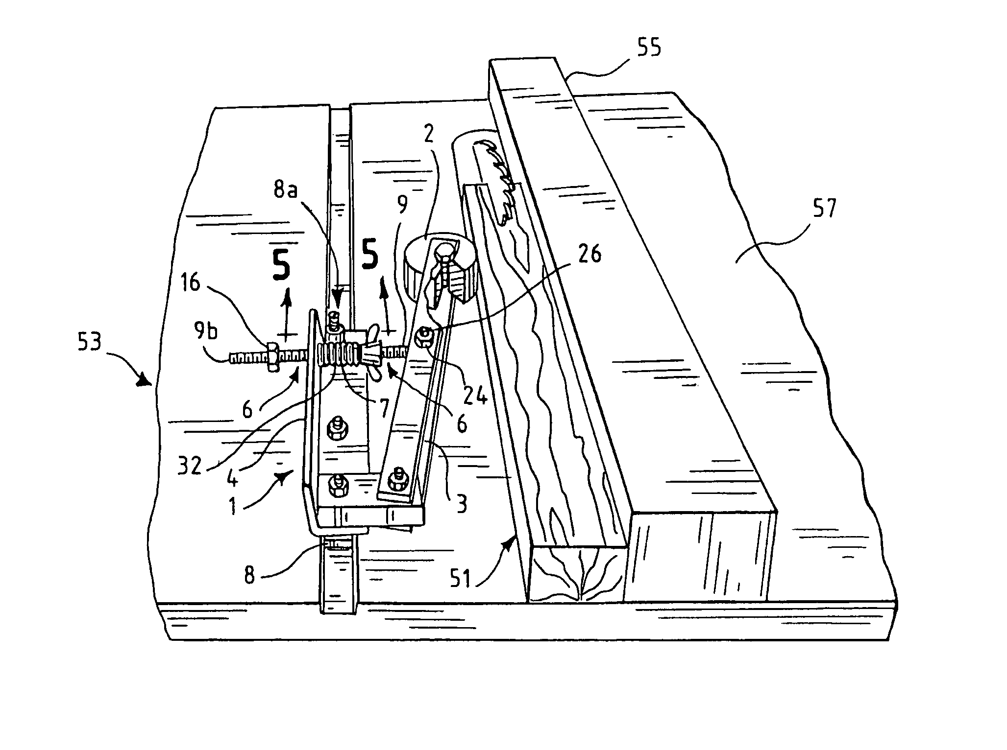
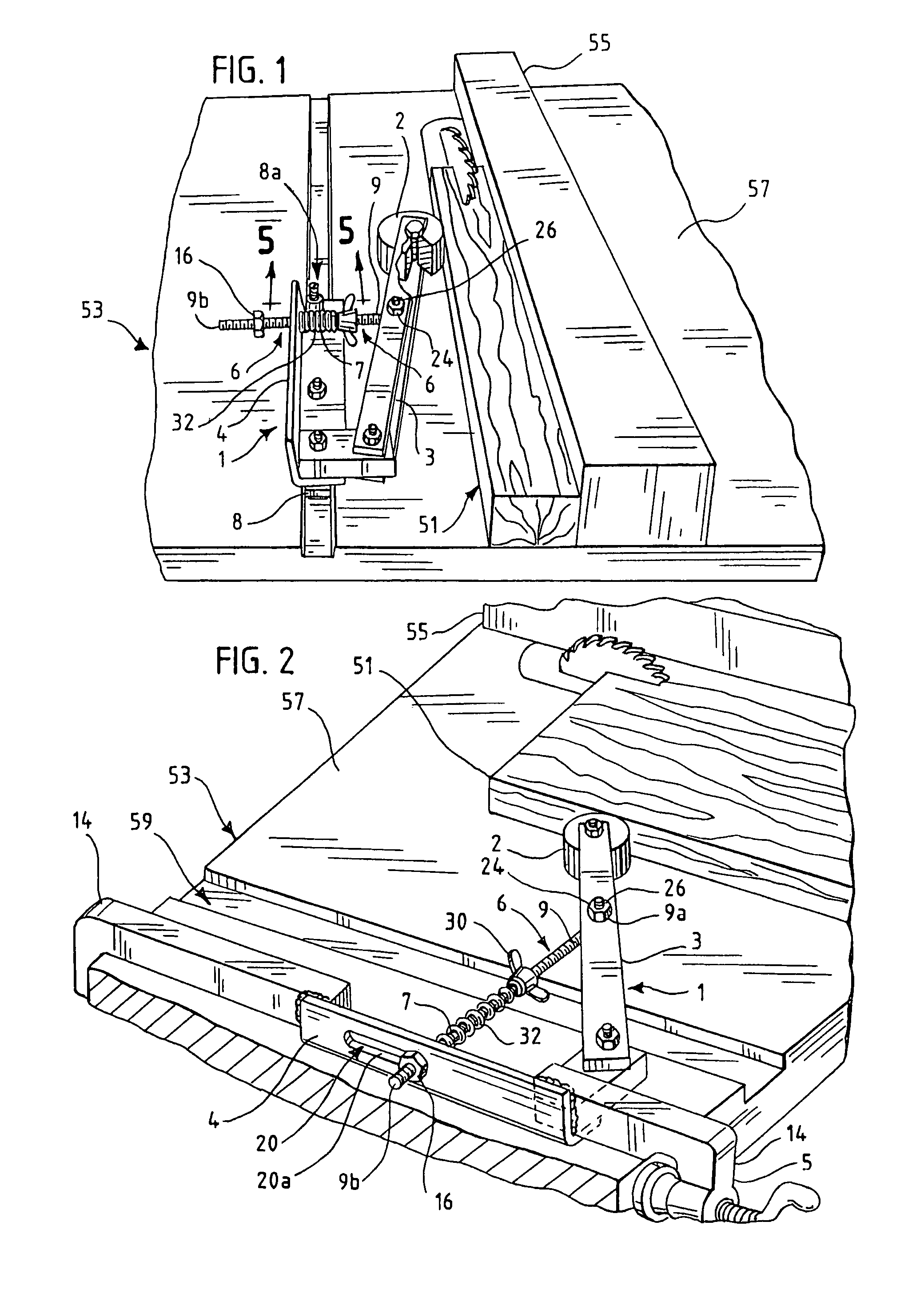
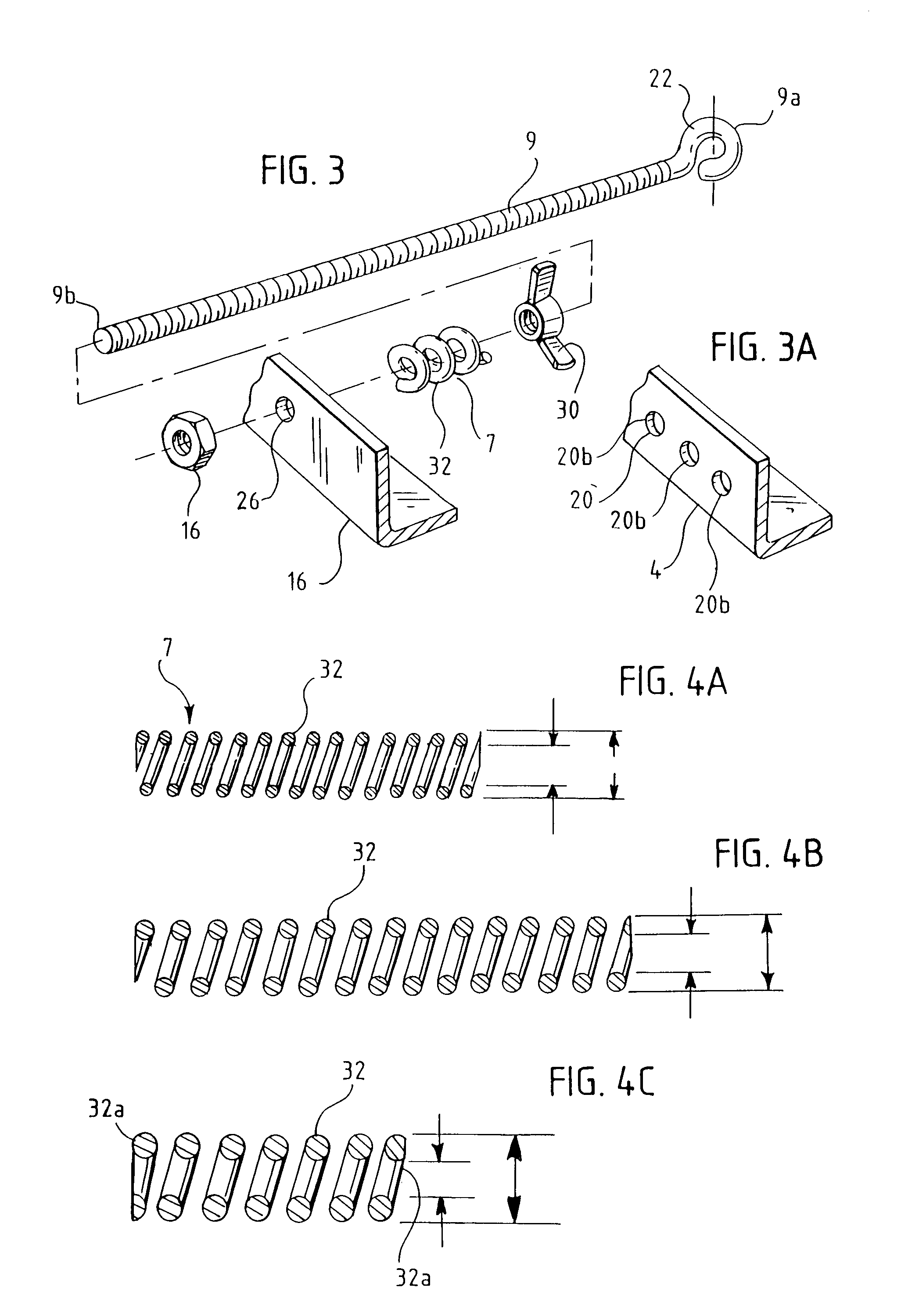
[0028]According to one embodiment, a horizontal hold down jig 1, for use in horizontally guiding a piece of wood 51 to be cut on one of a portable table saw 53 and a portable router table having a moveable rip fence 55, comprising a rotatable wheel 2 secured proximate a distal end of a first tension arm 3, a base plate 4 rotatably connected to a proximate end of the first tension arm, means to secure 5 the base plate 4 of the jig to a table 57, spreader means 6 for positioning the rotatable wheel 2 at a spaced distance from the base plate 4 when the base...


PUM

PropertyMeasurementUnit
ninety degree angleaaaaaaaaaa
tensionaaaaaaaaaa
distanceaaaaaaaaaa

Abstract

A horizontal rotary hold down jig for use in horizontally guiding a piece of wood to be cut on one of a portable table saw and a portable router table comprising a spring biased rotatable wheel that can be secured to the table. The spring biasing can be adjusted to provide uniform or enhanced pressure through use of a plurality of substitutable compression springs of varying compressive strength characteristics to laterally stabilize a piece of wood of varying consistency, wood grain angle, feed cutting speed, width, and thickness or depth of cut.

Description

BACKGROUND OF THE INVENTION[0001]Many woodworking methods such as routing, joining and cutting involve the step of moving a workpiece past a rotating cutting tool. These operations are typically performed on a woodworking machine having a table. Examples of such machines include routertables, shapers, joiners, jointers, and table saws. Examples of rotating cutting tools include saw blades and router bits.[0002]When performing a woodworking operation on a table such as routing, joining and cutting the machine operator must control the path of the workpiece as it moves relative to the cutting tool. The motion of the workpiece is typically guided in whole ore in part by hand. In some cases a motion guide may be utilized to aid the machine operator in guiding the motion of the workpiece. Examples of motion guides include fences, and featherboards.[0003]A fence is typically an elongate metallic member which is fixed to the table of a machine. The fence typically includes an elongate, fla...

Claims


Application Information

Patent Timeline
Patent Type & Authority Patents(United States)
IPC IPC(8): B27C1/12
CPCB27B25/02B27C5/06Y10T83/743Y10T83/745
Inventor VILLIGER, ERIC J.
Owner VILLIGER ERIC J
Why Eureka
Try Eureka