
Double-sided door braking equipment for a operator

a double-sided, door-operating technology, applied in the direction of braking systems, door/window protective devices, wing accessories, etc., can solve the problems of insufficient braking force of using single-sided braking equipment, and insufficient braking force of a door-operating door with relatively higher loads. , to achieve the effect of improving the braking effect of conventional braking equipment, increasing costs, and increasing brakeag

Active Publication Date: 2008-03-11
HSIEH CHUNG HSIEN
View PDF5 Cites 13 Cited by
  • Summary
  • Abstract
  • Description
  • Claims
  • Application Information

AI Technical Summary

Benefits of technology

The double-sided braking equipment enhances braking performance, reduces wear on brake linings, and extends the lifespan of the braking components by distributing the braking force more effectively, while maintaining a compact design and avoiding damage to the connection between the braking component and axle.

Problems solved by technology

Braking equipment of this type is only suitable for the door operator which is adapted for a small roll-up door or door panel.
The well-known braking equipments used for a door operator, such as the two braking equipments described above, provide the braking force only by a single braking pad being pushed against the braking component for the door operator, and the braking component is unmovable along an axle of the door operator and unrotatable with respect to the axle.
Nevertheless, using a single-sided braking equipment provides insufficient braking force to brake a door operator with relatively higher loads, such as large roll-up doors or large door panels.
This could result in problems related to safety.
The counteracting force acts on the connection continually and / or periodically, and thus the connection is possible to be damaged.
Consequently the wear rate of the brake lining of the braking component and the counteracting force applied on the connection are also increased.
The aforesaid will have negative effects to the braking equipment.

Method used


Image

  • Double-sided door braking equipment for a operator
  • Double-sided door braking equipment for a operator
  • Double-sided door braking equipment for a operator

Examples


Embodiment Construction

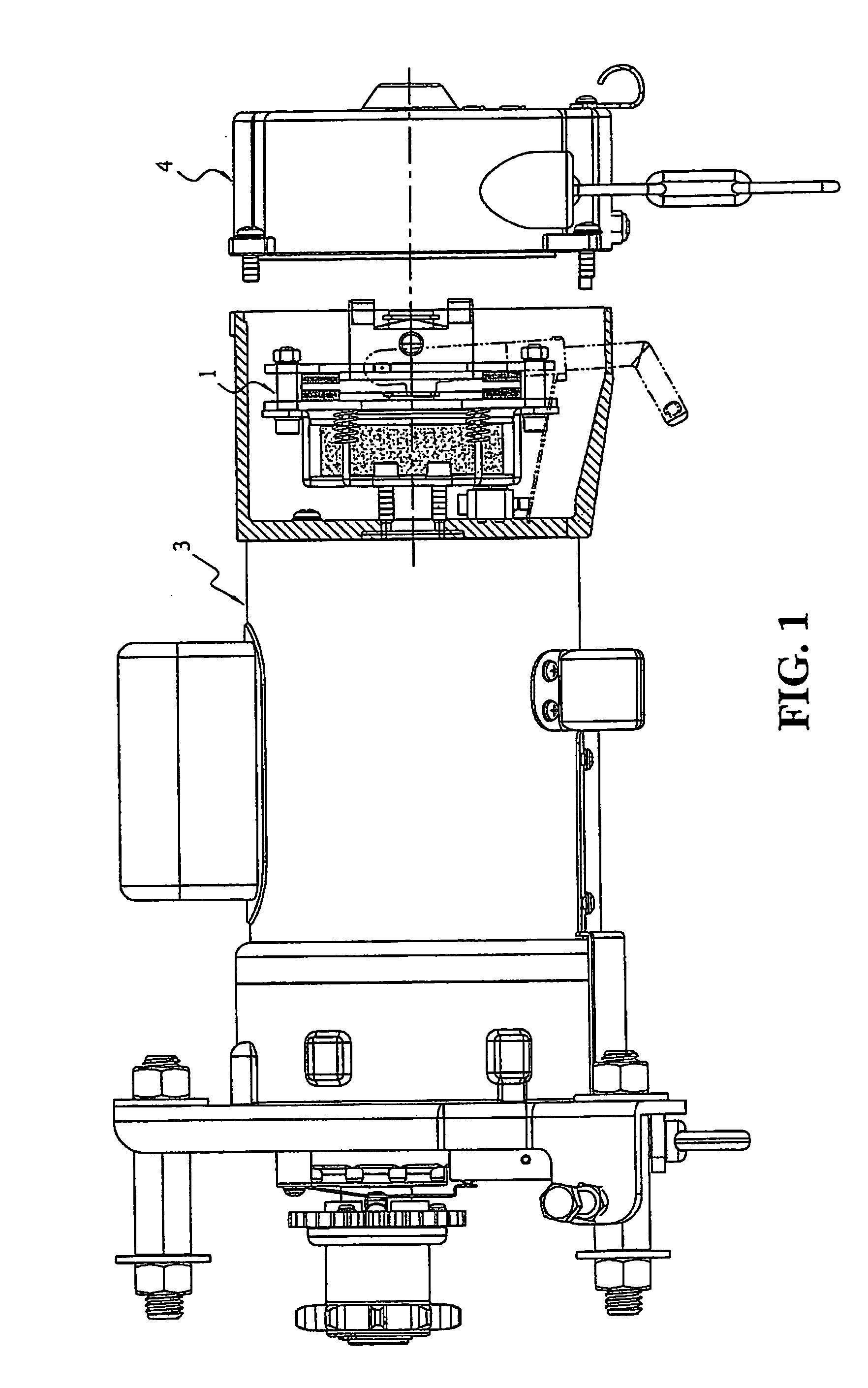
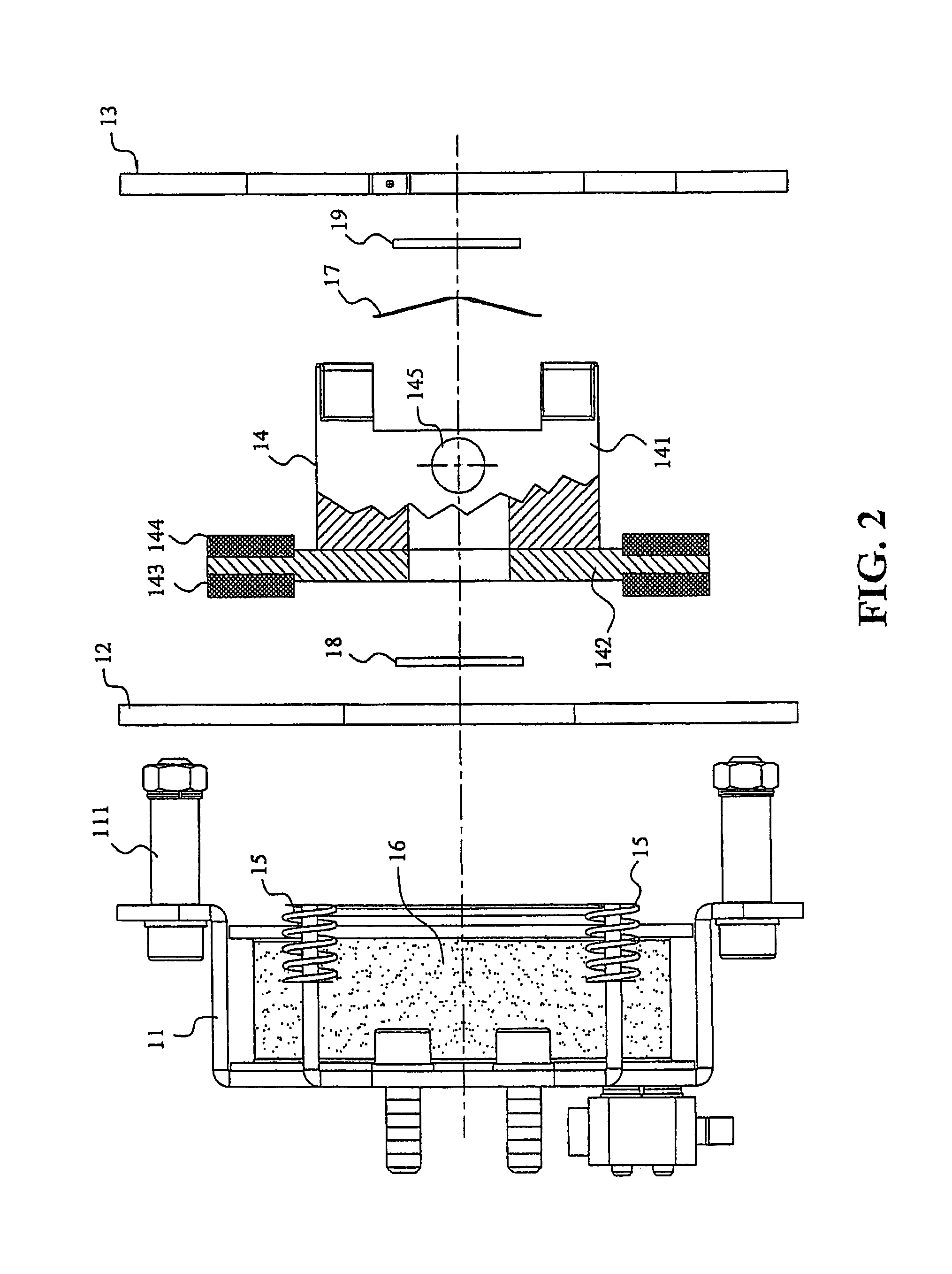
[0023]FIG. 1 is an exploded planar view of the door operator comprising a braking equipment and a pull-chain disk while FIGS. 2 and 5 respectively refer to exploded planar views of different embodiments.

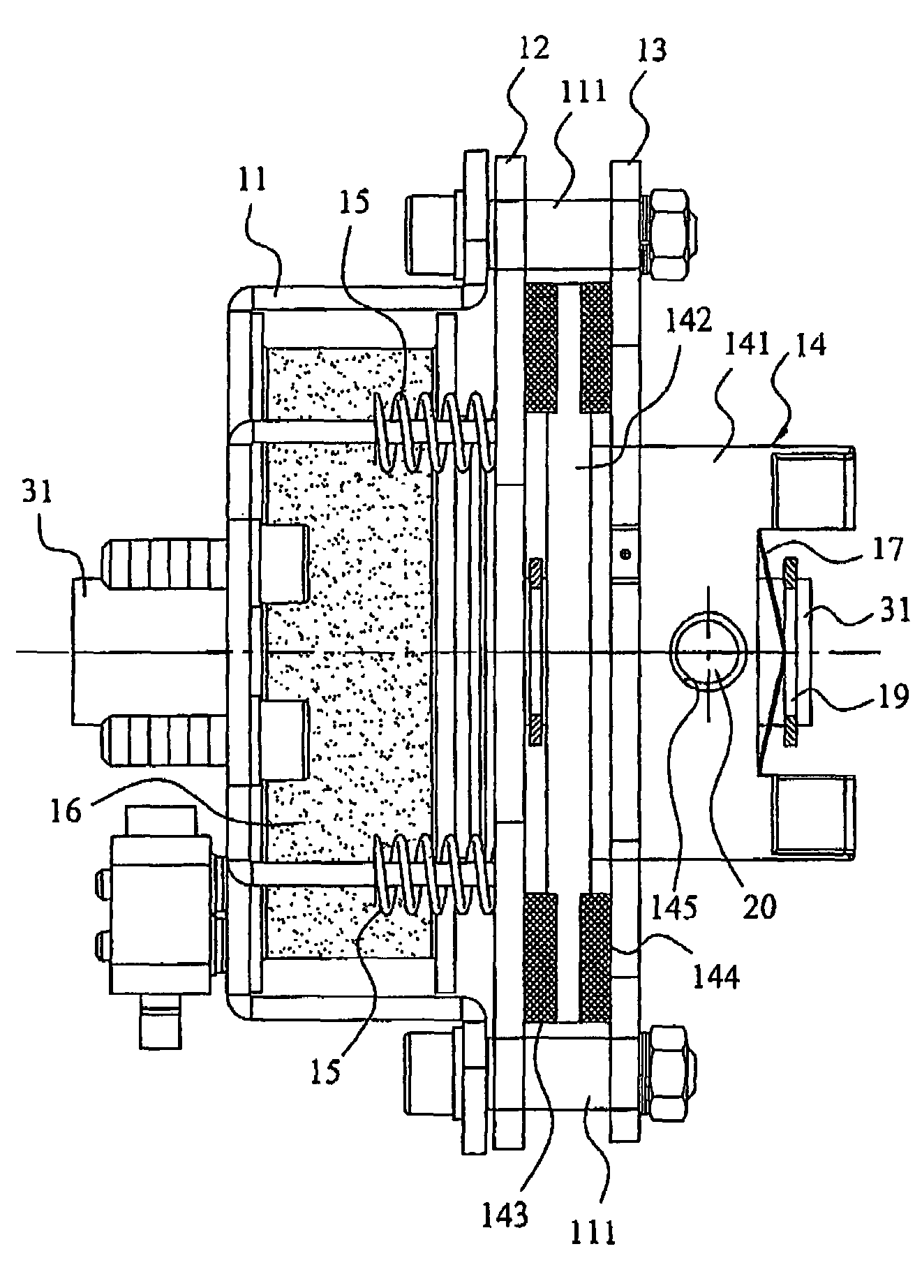
[0024]Referring to FIGS. 2 to 4, according to the preferred embodiment of the present invention a double-sided braking equipment 1 comprises: a supporting frame 11 with a plurality of guide bars 111; a first braking pad 12 which is movable in an axial direction of the axle 31 of the door operator 3 by being guided by the guide bars 111; a second braking pad 13 which is fixed to a tail end of the guide bars 111; a braking component 14 comprising an axle-connecting portion 141 and a braking disk 142; a first fastening ring 18 and a second fastening ring 19 that are respectively arranged on both sides of the braking component 14 on the axle 31 of the door operator 3; a fixing spring component 17; and an electromagnet 16 which enables the first braking pad 12 to be retracted.

[0025]The su...


PUM


Abstract

This invention relates to a double-sided equipment for a braking system, comprising a first braking pad, a second braking pad, a braking component, a fixing spring component, a compression spring, and an electromagnet, wherein the braking component located between the first braking pad and the second braking pad is movable along the axle of the door operator but is unrotatable with respect to the door operator axle. As a result of the compression spring, the first braking pad and the braking component will be pushed together towards the second braking pad, thereby the braking component is clamped from its two sides by the two braking pads. When the first braking pad is retracted by the electromagnet, the fixing spring enables the braking component to separate from the second braking pad, causing the braking component to be fully separated from the first and second braking pads.

Description

TECHNICAL FIELD[0001]This invention relates to a braking equipment for a door operator, particularly a double-sided braking equipment having a braking component with a braking disk which is movable axially.BACKGROUND OF THE INVENTION[0002]A door operator that is generally used for a vertical door, such as a vertically lifted roll-up door or a garage door, has at least one braking equipment used to brake the door operator and maintain the rolled-up door or door panel at a specific position or a stationary position. A braking equipment of this type, such as Applicant granted U.S. Pat. No. 6,055,885, is usually designed to retract a braking pad pushed by a spring to release a braking state by means of an electromagnet without the braking pad resting on a brake lining of a braking component during opening or closing a door through actuating the door operator. When the door operator stops running, and the electromagnet is switched off, the door operator is maintained in a braking state.[...

Claims


Application Information

Patent Timeline
Patent Type & Authority Patents(United States)
IPC IPC(8): B60T13/04
CPCE05F15/665E06B9/88E05F15/40E05Y2201/21E05Y2201/246E05Y2201/26E05Y2201/266F16D2121/22E05Y2201/462E05Y2900/106E05Y2900/00
Inventor HSIEH, CHUNG-HSIEN
Owner HSIEH CHUNG HSIEN
Learn More